Interactive Hexagon Grid Tutorial Part 4 - Hexagon Shader
Greetings, friends! In the previous three lessons, we learned how to make an interactive hexagon grid using the 2D HTML Canvas, but now it's time to start making a hexagon grid using the power of WebGL and hardware acceleration.
Introduction
This tutorial is the beginning of a new way of creating interactive hexagon grids. If you haven't read the past three tutorials, that's okay! You can start here if you're only interested in using shaders to make a hexagon grid.
In this tutorial, we'll learn how to make a hexagon in a fragment shader using Shadertoy and the OpenGL Shading Language (GLSL). In the next tutorial, we'll learn how to make a grid of hexagons. Then, we'll learn how to port Shadertoy code to Three.js.
Go ahead and throw away almost everything you learned in the previous three tutorials because where we're going, we don't need the 2D HTML canvas anymore. Just kidding...the previous three tutorials still taught useful skills about hexagon geometry. Read them if you're curious 🙂
Anyways, let's head off to a new adventure: to the land of shaders!
Review of GLSL
If you need a review of GLSL and Shadertoy, I highly recommend reading my Shadertoy Tutorial Series. This series will teach you the fundamentals of Shadertoy and how to make shaders using GLSL. Once you feel confident enough in GLSL, come back here!
Make sure to at least read Part 1 through Part 4 and Part 15 which discusses how to use channels, textures, and buffers in Shadertoy.
Starting a New Shader
Let's create a brand new shader in Shadertoy by going to https://www.shadertoy.com/new. Then, replace the default code with the following:
void mainImage(out vec4 fragColor, in vec2 fragCoord)
{
    vec3 col = vec3(0);

    // Normalized pixel coordinates (from 0 to 1)
    vec2 uv = fragCoord/iResolution.xy;

    fragColor = vec4(col,1.0);
}
This code simply sets the color for every pixel to black in the Shadertoy canvas. When starting a new shader in Shadertoy, the UV coordinates (the uv variable) of the canvas are normalized between zero and one across both the x-axis and y-axis, but we can adjust this range as we'll see later.
In shaders, the convention is typically that the x-axis increases as you go to the right. The y-axis increases as you go up which is opposite to the 2D HTML canvas where the y-direction increases as you go down. Keep this in mind when developing a hexagon grid using shaders.
Understanding the Dot Product
We will use the dot product to help make a hexagon, but let's first understand what it represents. By definition, the dot product between two vectors is equal to the sum of the products of each component of a vector. For example, our uv variable is a two-dimensional vector with a x-component and y-component. If we take the dot product of the vector, uv, and itself, it produces the following result:
dot(uv, uv)
  = uv.x * uv.x + uv.y * uv.y
  = uv.x ^ 2 + uv.y ^ 2
Let's look at another example. We'll take the dot product between vec2(1, 2) and vec2(3, 4).
dot(vec2(1, 2), vec2(3, 4))
  = 1 * 3 + 2 * 4
  = 3 + 8
  = 11
We multiply the x-component of the first vector with the x-component of the second vector. Then, we multiply the y-component of the first vector with the y-component of the second vector. The result is the sum between the two products.
What does the dot product tell us? What is the meaning of 11 in the dot product between vec2(1, 2) and vec2(3, 4)? When we calculate the dot product, we get back a scalar value. That is, we get back a regular number that is not a vector. This number can tell us a relation between the two vectors.
If the dot product between two numbers is zero, then we know the vectors are completely perpendicular with each other. If the dot product is a negative value, then the vectors are mostly facing opposite directions. If the product is positive, then the vectors are mostly facing toward the same direction.
Let's look at a visual example of this. Suppose we wanted to take the dot product between uv and vec2(0, 1). If we do some basic calculations, we can see that the x-component of uv goes away, and we're only left with the y-component of uv.
dot(uv, vec2(0, 1))
  = uv.x * 0 + uv.y * 1
  = uv.y
Let's visualize this dot product using GLSL code in Shadertoy.
void mainImage( out vec4 fragColor, in vec2 fragCoord )
{
    vec3 col = vec3(0);

    vec2 uv = fragCoord/iResolution.xy;

    float d = dot(uv, vec2(0, 1));

    col = vec3(d);

    fragColor = vec4(col,1.0);
}
After running this code, we should see a vertical gradient appear in the canvas.
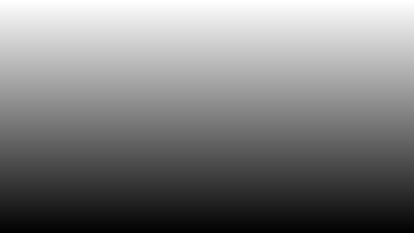
As the y-component of uv increases, the color becomes white. That is because we are taking the dot product everywhere in the canvas. For pixels that closely aligns with vec2(0, 1), their color will be more white. The top of the canvas has a coordinate of one. The bottom of the canvas has a coordinate of 0. Pixels with UV coordinates that are farther away from vec(0, 1) will therefore have a darker color.
The dot product therefore acts like a "signed distance function" (or SDF). It also shows us how closely aligned vectors are with each other. This is why you typically see the dot product expressed in terms of another equation:
dot(a, b) = length(a) * length(b) * cos(theta)
Where a and b are vectors and theta is the angle between the two vectors. If you were making a video game, you could make the character's line of sight a vector. If an enemy is within a few degrees of this line of sight, then you know the enemy is within attacking range.
Every pixel is a vector that is relative to the origin of the canvas. Currently, our UV coordinates are setup such that the origin is at the bottom-left corner of the canvas. This is why the pixels get darker when they're close to the bottom of the canvas.
Remapping our UV Coordinates
Currently, our UV coordinates go betwen zero and one on both the x-axis and y-axis. Let's make them go between -1 and 1 instead. This will let us create a coordinate space with four quadrants instead of just one.
void mainImage( out vec4 fragColor, in vec2 fragCoord )
{
    vec3 col = vec3(0);

    vec2 uv = fragCoord/iResolution.xy * 2. - 1.;

    float d = dot(uv, vec2(0, 1));

    col = vec3(d);

    fragColor = vec4(col,1.0);
}
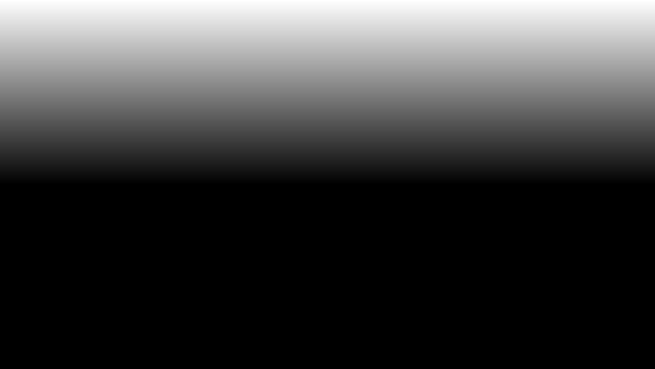
2. (with a decimal point) instead of 2 because GLSL expects a float to have a decimal in it when we're doing calculations that involve floats.When we run the code, you may have noticed that the gradient has shifted. That is because the x-axis equals zero in the middle of the canvas instead of the bottom of the canvas. When the final color is produced, color values less than zero are clamped to black, and color values greater than one are clamped to white.
When working with shaders, coordinate space transformations are the key to drawing lots of shapes. It's like we're bending or warping space instead of drawing paths. This is a completely different approach than drawing shapes using the 2D HTML canvas and an entirely different way of thinking. Keep practicing, and it'll become second nature.
Drawing a Diamond
It's time to find the diamond in the rough. I mean, it's time to draw a diamond which might get rough lol. Why a diamond? Because drawing a diamond is one step closer to drawing a hexagon. We'll see why soon.
Now that we have remapped our UV coordinate space, let's try splitting the screen between black and white colors using the power of the dot product.
void mainImage( out vec4 fragColor, in vec2 fragCoord )
{
    vec3 col = vec3(0);

    vec2 uv = fragCoord/iResolution.xy * 2. - 1.;

    float d = dot(uv, vec2(0, 1));
    float dStep = step(0., d);

    col = vec3(dStep);

    fragColor = vec4(col,1.0);
}
When we run this code, we can clearly see the canvas has been split between black and white, a yin-yang colored rectangle, if you will ☯.

The step is a powerful function used in shader programming. It accepts two parameters: an edge and a value, x. If x is less than edge, a value of zero is returned. Otherwise, it will return a value of one.
We can actually control where the boundary lies by changing the 0. in our step function to something a bit higher such as 0.2. Let's see how the canvas looks after this change.

Remember, the split between colors was made possible by the dot product. Let's now try making the boundary have a slope instead of a completely horizontal line. We can create such a boundary by using a diagonal vector in the dot product.
void mainImage( out vec4 fragColor, in vec2 fragCoord )
{
    vec3 col = vec3(0);

    vec2 uv = fragCoord/iResolution.xy * 2. - 1.;

    float d = dot(uv, vec2(0.5 * sqrt(3.), 0.5));
    float dStep = step(0.2, d);

    col = vec3(dStep);

    fragColor = vec4(col,1.0);
}
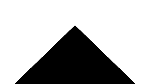
When we run this code, we should see the following image.
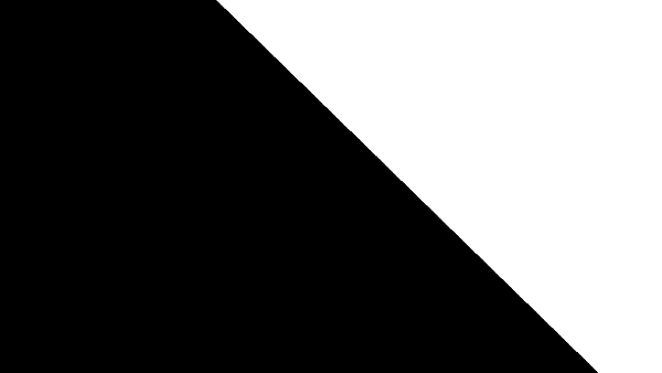
You might be wondering where the vector, vec2(0.5 * sqrt(3.), 0.5), came from. We can draw a triangle inside the hexagon such that the slanted edge of the hexagon is the hypotenuse of the triangle.
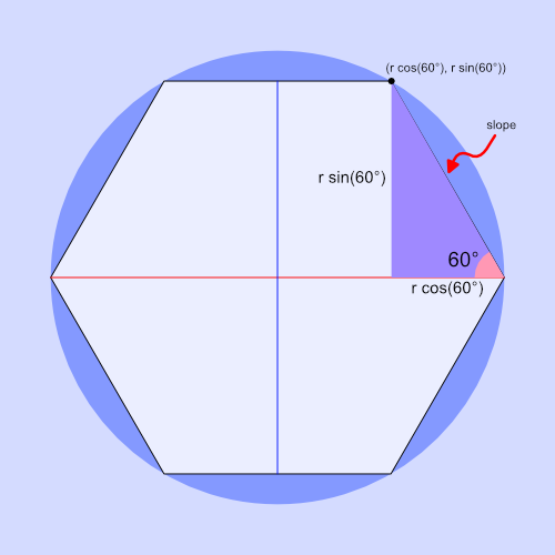
What we care about is the hypotenuse of this triangle, which is the slope of the slanted edge of the hexagon. If you remember from school, the slope is typically "rise over run" which means we would find the slope by dividing the height of the triangle by the base. However, we're making a shader, so we can represent the slope as a vector.
For a hexagon circumscribed by a circle with a radius of one, the height of the triangle is equal to 0.5 * sqrt(3), and the base is equal to 0.5. Therefore, we can represent the slope of the hexagon's slanted edge as the vector, vec2(0.5 * sqrt(3), 0.5). We can then use the slope as a diagonal line that splits the canvas in two.
With the canvas split with a diagonal line, it seems like we kinda have a quarter of a diamond. How do we make it a full diamond? We fold/warp space again using the power of math! Since our UV coordinates are currently setup to go between -1 and 1, we can take the absolute value of the UV coordinates to make each quadrant of our coordinate system equal to mirror images of the top-right quadrant.
Let's see what happens when we take the absolute value of uv along only the x-axis.
void mainImage( out vec4 fragColor, in vec2 fragCoord )
{
    vec3 col = vec3(0);

    vec2 uv = fragCoord/iResolution.xy * 2. - 1.;
    uv.x = abs(uv.x);

    float d = dot(uv, vec2(0.5 * sqrt(3.), 0.5));
    float dStep = step(0.2, d);

    col = vec3(dStep);

    fragColor = vec4(col,1.0);
}
After running the code, it looks like we have the top half of a diamond now!
We are effectively using the absolute value to trim away parts of the graph to make a shape. This is similar to the techniques people use to draw artwork in Desmos. By taking the absolute value of the x-component, we can effectively mirror a function across the y-axis.
Let's now take the absolute value of both components of the uv vector. This will mirror the top half of the diamond across the y-axis to form a complete diamond.
void mainImage( out vec4 fragColor, in vec2 fragCoord )
{
    vec3 col = vec3(0);

    vec2 uv = fragCoord/iResolution.xy * 2. - 1.;
    uv = abs(uv);

    float d = dot(uv, vec2(0.5 * sqrt(3.), 0.5));
    float dStep = step(0.2, d);

    col = vec3(dStep);

    fragColor = vec4(col,1.0);
}
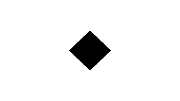
Yay! We have a small little diamond now! We can easily control the size by adjusting the first parameter of the step function. The next step is to cut off pieces of the top and bottom parts of the diamond to make our hexagon.
Drawing a Hexagon
We drew a diamond by using the dot product and warping space (the UV coordinate system), so now let's slice off the pointy parts of the diamond using the max function in GLSL.
void mainImage( out vec4 fragColor, in vec2 fragCoord )
{
    vec3 col = vec3(0);

    vec2 uv = fragCoord/iResolution.xy * 2. - 1.;
    uv = abs(uv);

    float d = max(dot(uv, vec2(0.5 * sqrt(3.), 0.5)), uv.y);
    float dStep = step(0.2, d);

    col = vec3(dStep);

    fragColor = vec4(col,1.0);
}
If you run this code, we should have a hexagon! Kinda. It seems a bit squashed...

Fixing the Aspect Ratio
The reason for the distortion is due to the aspect ratio of the Shadertoy canvas. The Shadertoy canvas typically has a width/height ratio of 16/9. We need to correct for the difference in size between the width and height. We can do this by changing the uv variable at the top of our code.
vec2 uv = (fragCoord - iResolution.xy * .5) / iResolution.y;
Assuming an aspect ratio of 16/9, our UV coordinates along the x-axis will range between approximately -0.88 and 0.88. The y-axis will range between -0.5 and 0.5. Our code should now look like the following.
void mainImage( out vec4 fragColor, in vec2 fragCoord )
{
    vec3 col = vec3(0);

    // Take aspect ratio into consideration
    vec2 uv = (fragCoord - iResolution.xy * .5) / iResolution.y;
    uv = abs(uv);

    float d = max(dot(uv, vec2(0.5 * sqrt(3.), 0.5)), uv.y);
    float dStep = step(0.2, d);

    col = vec3(dStep);

    fragColor = vec4(col,1.0);
}
Once we run this code, we should have a regular hexagon. Behold! A shader-driven hexagon! ⬣
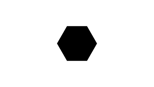
In the max function, we're taking the max between the function used to draw the diamond and a value of uv.y. Since we're setting uv = abs(uv), we are effectively trimming the top and bottom of the hexagon at the same time using a horizontal line at y = 0.2 and y = -0.2. It's like we took a saw and sliced off the pointy parts of the diamond.
The first parameter we pass into the step function will control the size of the hexagon. A value of 0.2 will make the hexagon have a total height of 0.4.
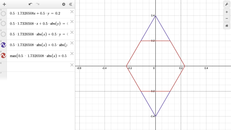
Please see this Desmos graph I made if you would like to get more insight into how we made our hexagon. You can hide/show different functions in the graph. By using a combination of absolute values and the max function, we are able to create a plot of a hexagon.
Code Cleanup
Let's move our logic for building a hexagon in our shader to a function called hexD (for hexagonal distance) because we will need to utilize it later when we start creating a hexagon grid.
We'll also create a global variable at the top of the shader called hexSide that will store the vector, vec2(1.7320508, 1). This vector is double of the vector we were using previously to make our hexagons. Therefore, we need to multiply it by 0.5 in our dot product. We're using the doubled version of the vector because it will be more useful later on.
Our finished code should look like the following.
const vec2 hexSide = vec2(1.7320508, 1); // proportion between the two legs of a 30-60-90 triangle

// hexagonal distance
float hexD(in vec2 p)
{
    p = abs(p);

    return max(dot(p, hexSide * .5), p.y);
}

void mainImage( out vec4 fragColor, in vec2 fragCoord )
{
    vec3 col = vec3(0);

    // Take aspect ratio into consideration
    vec2 uv = (fragCoord - iResolution.xy*.5)/iResolution.y;

    float d = hexD(uv);
    float dStep = step(0.2, d);

    col = vec3(dStep);

    fragColor = vec4(col,1.0);
}
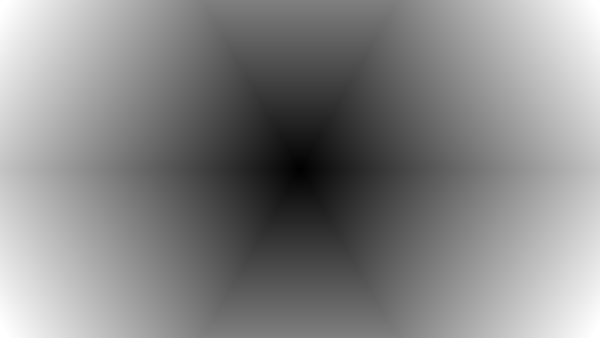
We have now created our very own hexagon signed distanced field/function (SDF). We can use the hexD function to get the distance between the center point of the hexagon and an edge of the hexagon. We can visualize the signed distance field by looking at the color of d instead of dStep:
col = vec3(d);
We can see that the colors are darker toward the center of the hexagon and get brighter as you move toward the edges or corners of the hexagon.
Conclusion
In this tutorial, we learned how to make an SDF for a hexagon. This lets us detect the distance between the center of the hexagon and its edges and corners. This will be useful later when we start implementing an interactive hexagon grid.
In the next tutorial, we'll learn how to convert our cartesian coordinates into hexagonal coordinates. I'll put the "nate" in coordinate! Get it? Because my nickname is Nate. Funny, right? 😅
Wait, no, don't leave! See you over at the next tutorial! Right? Yes? Yes.