Interactive Hexagon Grid Tutorial Part 6 - Mouse Interactions and Multi-pass Shaders
Greetings, friends! In this tutorial, we'll learn how to make an interactive hexagon grid using the power of shaders! ✨
In the previous tutorial, we learned how to build a hexagon grid by bending UV coordinates to our will. Does that make us UV benders? That sounds like a cool job title. Anyways! Let's learn how to make our hexagon grid light up like magic!
Using the Mouse in Shadertoy
Alright, we won't start making our hexagon grid light up just yet. Sorry for the detour, but we need to learn how to use the mouse in Shadertoy!
Let's create a new shader in Shadertoy. We'll start with the following code:
void mainImage( out vec4 fragColor, in vec2 fragCoord )
{
    vec3 col = vec3(0);

    // Normalized pixel coordinates (from 0 to 1)
    vec2 uv = fragCoord/iResolution.xy;

    // Normalized mouse coordinates (from 0 to 1)
    vec2 m = iMouse.xy/iResolution.xy;

    col = vec3(m, 0);

    fragColor = vec4(col,1.0);
}
If you click on the Shadertoy canvas and move your mouse around, you'll see the color start to change. Make sure the left-click of your mouse is held down while moving it though.
Shadertoy doesn't support mouseover events like in JavaScript. That is because Shadertoy was only programmed to handle mouse clicks and mouse positions. When we work with Three.js, we'll have the ability to pass whatever data we want to the shader. In Shadertoy, however, we're limited to what the creators give us.
Notice how we have a line of code that references a new variable of type vec4 called iMouse. This variable is built into Shadertoy and gives us important information about the state of the mouse.
The x and y components of iMouse gives us the x and y coordinates of our mouse with respect to the Shadertoy canvas. The z-component and w-components tell us information about the mouse being held down or recently clicked. For this tutorial, we only care about the x and y components of iMouse.
The value of iMouse.xy ranges between 0 and iResolution.x along the x-axis and 0 and iResolution.y along the y-axis. Therefore, the mouse coordinates can go up to 1024 if your Shadertoy canvas is 1024 pixels wide. We can normalize the mouse coordinates to stay in a range between zero and one by dividing by iResolution.
The variable, m, is the UV coordinate of our mouse. It will change when the user clicks anywhere in the Shadertoy canvas. Similar to regular UV coordinates we commonly define in the uv variable, we can normalize the variable, m, to any range of values we want. In this tutorial, we'll keep uv and m very similar.
If we fix the aspect ratio of uv, then we should fix the aspect ratio of m.
void mainImage( out vec4 fragColor, in vec2 fragCoord )
{
    vec3 col = vec3(0);

    vec2 uv = (fragCoord - iResolution.xy * .5) / iResolution.y;
    vec2 m = (iMouse.xy - iResolution.xy * .5) / iResolution.y;

    col = vec3(m, 0);

    fragColor = vec4(col,1.0);
}
Highlighting Hexagons with the Mouse
Alright! Time to light up the hexagon grid with the mouse! Let's retrieve the code from the end of the previous tutorial. It should look like the following:
const vec2 hexSide = vec2(1.7320508, 1); // proportion between two sides of 30-60-90 triangle

// hexagonal distance
float hexD(in vec2 p)
{
    p = abs(p);

    return max(dot(p, hexSide * .5), p.y);
}

// hexagonal coordinates
vec4 hexC(vec2 p)
{
    // hexagon centers
    vec4 hc = floor(vec4(p, p - vec2(hexSide.x/2., .5)) / hexSide.xyxy) + .5;

    // rectangular grids
    vec4 rg = vec4(p - hc.xy * hexSide, p - (hc.zw + .5) * hexSide);

    // hexagonal grid and IDs
    return dot(rg.xy, rg.xy) < dot(rg.zw, rg.zw)
        ? vec4(rg.xy, hc.xy)
        : vec4(rg.zw, hc.zw + .5);
}

void mainImage( out vec4 fragColor, in vec2 fragCoord )
{
    vec3 col = vec3(0);

    vec2 uv = (fragCoord - iResolution.xy * .5)/iResolution.y;

    uv *= 5.;

    vec4 h = hexC(uv);

    col = vec3(h.zw * 0.2 + 0.5, 1);

    fragColor = vec4(col,1.0);
}
Currently, we're drawing different colored hexagons to the canvas using each hexagon's ID to determine a color. Let's now visualize the hexagon distance in each hexagon. We'll update our mainImage function to the following:
void mainImage( out vec4 fragColor, in vec2 fragCoord )
{
    vec3 col = vec3(0);

    vec2 uv = (fragCoord - iResolution.xy * .5)/iResolution.y;

    uv *= 5.;

    vec4 h = hexC(uv);

    float d = hexD(h.xy);

    col = vec3(d);

    fragColor = vec4(col,1.0);
}
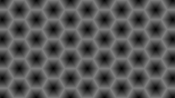
When we execute this code, we should see a grid of hexagons and the "signed distance fields" (SDF) inside each hexagon. The closer we are to each hexagon's center, the darker the color appears. As we approach the edges of the hexagon, the color gets brighter.
We can use the step function to create solid colors. As you may recall, the step function is equal to zero if the second parameter is less than the first parameter. Otherwise, a value of one is returned. Let's use the step function to draw outlines around each hexagon.
void mainImage( out vec4 fragColor, in vec2 fragCoord )
{
    vec3 col = vec3(0);

    vec2 uv = (fragCoord - iResolution.xy * .5)/iResolution.y;

    uv *= 5.;

    vec4 h = hexC(uv);

    float d = hexD(h.xy);

    float dStep = step(0.5 - 10./iResolution.y, d);

    col = vec3(dStep);

    fragColor = vec4(col,1.0);
}
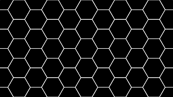
When we run this code, we should see a hexagon grid where each hexagon is black and has a white outline.
You might be curious as to why we're passing such a strange value to our step function.
float dStep = step(0.5 - 10./iResolution.y, d);
The maximum distance is around 0.5 for each hexagon, so we need to make an outline that is a bit smaller than 0.5. By subtracting 10./iResolution.y, we can effectively make our outline about 10 pixels thick across each side of the hexagon.
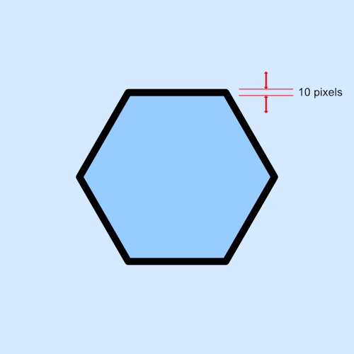
By using iResolution.y, we can make sure the outline looks crisp across any Shadertoy canvas sizes. Try making your shader full screen to see if the outlines still look sharp!
We can easily invert the colors using the following change to our dStep variable.
float dStep = 1. - step(0.5 - 10./iResolution.y, d);
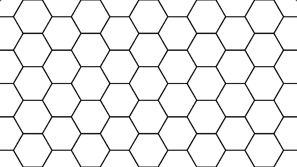
Since we're only dealing with black and white colors, it's easy to swap them. We should now see white hexagons with black outlines.
The next step is to add the iMouse variable, so we can make hexagons change colors when the mouse is touching them. Let's update the mainImage function to the following.
void mainImage( out vec4 fragColor, in vec2 fragCoord )
{
    vec3 col = vec3(0);

    vec2 uv = (fragCoord - iResolution.xy * .5)/iResolution.y;
    vec2 m = (iMouse.xy - iResolution.xy * .5)/iResolution.y;

    uv *= 5.;
    m *= 5.;

    vec4 h = hexC(uv);
    vec4 hm = hexC(m);

    float d = hexD(h.xy);

    float dStep = 1. - step(0.5 - 10./iResolution.y, d);

    col = vec3(dStep);

    if (h.zw == hm.zw) col = vec3(1, 0, 0);

    fragColor = vec4(col,1.0);
}
When we run the code, we should now be able to move our mouse (while holding left-click) anywhere on the Shadertoy canvas, and it'll light up! Yay!
Notice how the m variable is identical to uv everywhere inside our code. That is because the mouse coordinates are essentially another set of UV coordinates that need to be tracked. It will undergo the same transformations as the uv variable, so that we can convert the mouse coordinates into hexagonal coordinates. Then, we can obtain an ID for where the mouse is located and compare it with the IDs of every hexagon in the hexagon grid.
Multi-pass Shaders
So far, so good! We got our canvas to light up wherever the mouse is! But, how do we make cool color fade effects in a shader, similar to what we made in Part 2 of this tutorial series?
The answer is to use multi-pass shaders. This is just a colloquial term that means to run multiple shader programs back to back within a single frame (or however fast you can). In OpenGL (and by extension, WebGL), we need to load a fragment shader program into memory before we can compile it, execute it, and save the results to either the frame buffer or render textures.
Multi-pass shaders aren't the cheapest operation by any means because you'd want to minimize draw calls to the GPU as much as you can, but they can create some interesting postprocessing effects or other cool applications. In fact, some people on Shadertoy have implemented entire retro games in a fragment shader by leveraging multi-pass shaders!
Our multi-pass shader will be very minimal, so it'll still be very performant! Shadertoy provides a simple way to make multi-pass shaders without much setup on our part. Behind the scenes, it can save the output color of the fragment shader into a "render texture," so that we can use the color data in another fragment shader program.
To create a multi-pass shader in Shadertoy, click the little "+" (plus) sign to the left of the "Image" tab above your shader code. Then, click "Buffer A" to create a new shader pass.
We're going to move all of our current code into "Buffer A". Make sure the following code is moved to "Buffer A".
const vec2 hexSide = vec2(1.7320508, 1); // proportion between two sides of 30-60-90 triangle

// hexagonal distance
float hexD(in vec2 p)
{
    p = abs(p);

    return max(dot(p, hexSide * .5), p.y);
}

// hexagonal coordinates
vec4 hexC(vec2 p)
{
    // hexagon centers
    vec4 hc = floor(vec4(p, p - vec2(hexSide.x/2., .5)) / hexSide.xyxy) + .5;

    // rectangular grids
    vec4 rg = vec4(p - hc.xy * hexSide, p - (hc.zw + .5) * hexSide);

    // hexagonal grid and IDs
    return dot(rg.xy, rg.xy) < dot(rg.zw, rg.zw)
        ? vec4(rg.xy, hc.xy)
        : vec4(rg.zw, hc.zw + .5);
}

void mainImage( out vec4 fragColor, in vec2 fragCoord )
{
    vec3 col = vec3(0);

    vec2 uv = (fragCoord - iResolution.xy * .5)/iResolution.y;
    vec2 m = (iMouse.xy - iResolution.xy * .5)/iResolution.y;

    uv *= 5.;
    m *= 5.;

    vec4 h = hexC(uv);
    vec4 hm = hexC(m);

    float d = hexD(h.xy);

    float dStep = 1. - step(0.5 - 10./iResolution.y, d);

    col = vec3(dStep);

    if (h.zw == hm.zw) col = vec3(1, 0, 0);

    fragColor = vec4(col,1.0);
}
Next, replace all of the code inside the "Image" shader with the following code:
void mainImage( out vec4 fragColor, in vec2 fragCoord )
{
    vec3 col = vec3(0);

    vec2 uv = fragCoord.xy/iResolution.xy;

    vec3 data = texture(iChannel0, uv).xyz;

    col = data;

    fragColor = vec4(col,1.0);
}
Before running the code, we need to do one more thing. Make sure you're still in the "Image" shader. At the bottom of the page, there's a box that has the label, "iChannel0". Click on the box and select "Buffer A" from the "Misc" tab in the popup menu that appears.
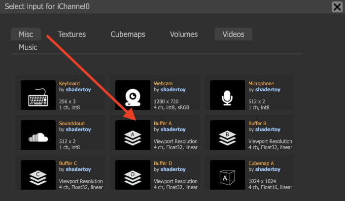
This will connect our shader pipeline such that the output of "Buffer A" is fed into the "Image" shader as a texture. After running the code, we should see the hexagon grid again as if nothing happened. Yay!
Let's review what we just changed. We moved all of our shader code to a new shader pass called "Buffer A". Then, we added "Buffer A" to the channel, "iChannel0". Inside the "Image" shader code, we pull data from the texture using the following line:
vec3 data = texture(iChannel0, uv).xyz;
This lets us access the first three components from the output of "Buffer A" which is the color that we draw to the Shadertoy canvas. We can pass any kind of information we want between shader passes, but we're limited to four data slots, one for each color: red, green, blue, and alpha.
When we use the mouse to hover over the Shadertoy canvas, we're going to store information about the active hexagon cell and pass it on over to the "Image" shader. Then, we're going to pass data from the "Image" shader back into the next frame of "Buffer A".
Currently, our multi-pass shader is configured as followed. For every frame, we have this render pipeline:
Current Frame of Buffer A ---> Image
We need the render pipeline to look like this:
Previous Frame of Buffer A ---> Current Frame of Buffer A ---> Image
Or, you can think of it like the following:
Buffer A ---> Image
        \
         \---> Next Frame of Buffer A
This cycle will repeat every frame or approximately 60 fps (unless your monitor's refresh rate is different).
Let's go back to the "Buffer A" tab. At the bottom of the screen, click on the "iChannel0" box. In the popup menu, select "Buffer A" again from the "Misc" tab. Now, our multi-pass shader is configured to pass data from the previous frame of Buffer A to the current frame.
We should see that in both the "Buffer A" shader and "Image" shader that "iChannel0" uses Buffer A as an input. We should be good to go now!
Creating a Color Fade Effect
Everything is in place for creating a color fade effect in Shadertoy. We just need to figure out which data to pass to the next frame of Buffer A and to the "Image" shader. I think the following three pieces of data are worthy candidates:
- All touched hexagons
- Output of
hexDfunction - A color multiplier to fade the color every frame
The fourth value can be anything you'd like. I'm going to leave it as 1.0. The three pieces of data I mentioned above need to go into the fragColor variable inside the "Buffer A" shader. That is how the data will be passed to the next frame of Buffer A and to the "Image" shader.
Let's change our code inside the "Buffer A" shader to be the following:
const vec2 hexSide = vec2(1.7320508, 1); // proportion between two sides of 30-60-90 triangle

// hexagonal distance
float hexD(in vec2 p)
{
    p = abs(p);

    return max(dot(p, hexSide * .5), p.y);
}

// hexagonal coordinates
vec4 hexC(vec2 p)
{
    // hexagon centers
    vec4 hc = floor(vec4(p, p - vec2(hexSide.x/2., .5)) / hexSide.xyxy) + .5;

    // rectangular grids
    vec4 rg = vec4(p - hc.xy * hexSide, p - (hc.zw + .5) * hexSide);

    // hexagonal grid and IDs
    return dot(rg.xy, rg.xy) < dot(rg.zw, rg.zw)
        ? vec4(rg.xy, hc.xy)
        : vec4(rg.zw, hc.zw + .5);
}

// draw hexagon grid and transfer data to "Image" pass
void mainImage(out vec4 fragColor, in vec2 fragCoord)
{
    vec3 col = vec3(0);

    vec2 uv = (fragCoord - iResolution.xy * .5) / iResolution.y;
    vec2 m = (iMouse.xy - iResolution.xy * .5) / iResolution.y;

    vec3 data = texture(iChannel0, fragCoord/iResolution.xy).rgb;

    vec4 h = hexC(uv * 5.);
    vec4 hm = hexC(m * 5.);

    float d = hexD(h.xy);

    float ac = 0.; // active coordinate

    float touchTimeMultiplier = data.z < 0.001 ? 0. : data.z * 0.95;

    // check if ID of the hexagon currently touched by the mouse is the
    // same as the ID of the hexagon the current pixel is closest to
    if (h.zw == hm.zw) {
        ac = step(0., d);
        touchTimeMultiplier = 1.;
    }

    fragColor = vec4(vec3(data.x + ac, d, touchTimeMultiplier), 1.0);
}
Let's go through the main changes that were made to the code. We added a line of code for grabbing data from the previous output of Buffer A.
vec3 data = texture(iChannel0, fragCoord/iResolution.xy).xyz;
This is very similar to how we grabbed data in the "Image" shader. Next, we added a variable called ac to store the active hexagonal coordinate.
float ac = 0.;
Then, we created a variable called touchTimeMultiplier.
float touchTimeMultiplier = data.z < 0.001 ? 0. : data.z * 0.95;
This value will drop to 95% of its value every frame. If the value goes below 0.001, we'll just drop it to zero to prevent any weird coloring effects in the Shadertoy canvas. The value of data.z is the third piece of data we're sending to fragColor in Buffer A. It is equal to the previous frame's touchTimeMultiplier value. When the mouse has moved away from a hexagon, then we'll start fading the color.
Next, we're performing some actions when the hexagon has been clicked by the mouse.
if (h.zw == hm.zw) {
    ac = step(0., d);
    touchTimeMultiplier = 1.;
}
We're setting the active coordinate equal to the entire distance value of the hexagon. We use step(0., d) because we want to pass the entire hexagon's distance value to the "Image" shader. We don't want to make an outline around this hexagon because we will use it for debugging purposes as we'll see later.
The touchTimeMultiplier variable is set back to 1. when the mouse touches it, so we can start the color transition effect all over again.
Finally, we're passing all the useful data to the fragColor variable, so that we can use this data in the next frame of Buffer A and the "Image" shader.
fragColor = vec4(vec3(data.x + ac, d, touchTimeMultiplier), 1.0);
The first data component keeps track of which hexagon we have already touched with the mouse. The second data component is the output of the hexD function, so we can draw the hexagons however we'd like. The third piece of data is the touchTimeMultiplier that we'll use inside a lerp function to gradually transition colors from one to another.
Now that we have all our data, let's use them in the "Image" shader! Replace the contents of the "Image" shader with the following code:
const vec3 hoverColor = vec3(.43, .73, .50);
const vec3 originalColor = vec3(1);
const vec3 targetColor = vec3(.65, .87, .93);

void mainImage( out vec4 fragColor, in vec2 fragCoord )
{
    vec3 col = vec3(0);

    vec2 uv = fragCoord.xy/iResolution.xy;

    vec3 data = texture(iChannel0, uv).xyz;

    vec3 lerpedCol = mix(targetColor, hoverColor, data.z);

    float d = 1. - step(0.5 - 10./iResolution.y, data.y);

    if (data.x > 0.) {
        col = vec3(d) * lerpedCol;
    } else {
        col = vec3(d) * originalColor;
    }

    fragColor = vec4(col, 1.0);
}
Congrats! You made a complete interactive hexagon grid in a fragment shader! Hold down the mouse button on the Shadertoy canvas, and move the mouse around to see the cool effect!
Looks very similar to the interactive hexagon grid we created in Part 2, huh? I made sure to choose the same colors and everything 😁
Let's review how the code in the "Image" shader works. We first grab data from Buffer A using the following line:
vec3 data = texture(iChannel0, uv).xyz;
Then, we create a lerpedCol variable that will use the mix function to interpolate between colors using data.z, which stored the value of touchTimeMultiplier from Buffer A.
vec3 lerpedCol = mix(targetColor, hoverColor, data.z);
Notice how similar this function behaves to the lerp function we made in Part 2 of this tutorial series? That's because the lerp function we made in JavaScript takes inspiration from the mix function in GLSL and the lerp function in HLSL.
Next, let's look at the following lines of code:
if (data.x > 0.) {
    col = vec3(d) * lerpedCol;
} else {
    col = vec3(d) * originalColor;
}
We are using a conditional statement to check if data.x, the distance function of a hexagon, is greater than zero. If so, then we have determined that the hexagon has indeed been touched by the mouse, which should trigger the color fade effect to begin. The color fade will "stop" on its own thanks to following inequality we used in Buffer A.
float touchTimeMultiplier = data.z < 0.001 ? 0. : data.z * 0.95;
If the hexagon has not been touched, then its color will be set to originalColor.
We can easily debug which hexagons have been touched by adding the following code to the bottom of the "Image" shader, right before the fragColor.
// ...other code in mainImage function...

col = vec3(data.x);

fragColor = vec4(col, 1.0);
This will let us see a black and white representation of our hexagon grid. The hexagons start as black, but they turn white after being touched by the mouse. Reset/rewind the shader back to the beginning if you want to clear any "saved state" in the Shadertoy canvas.
Finished Code
Below, you can find the finished code for the "Buffer A" shader. I created a constant variable called scale and moved it to the top of the code. That way, we can multiply uv and m by the same scaling factor without having to change it in multiple places.
const vec2 hexSide = vec2(1.7320508, 1); // proportion between two sides of 30-60-90 triangle
const float scale = 5.; // hexagon grid scale factor

// hexagonal distance
float hexD(in vec2 p)
{
    p = abs(p);

    return max(dot(p, hexSide * .5), p.y);
}

// hexagonal coordinates
vec4 hexC(vec2 p)
{
    // hexagon centers
    vec4 hc = floor(vec4(p, p - vec2(hexSide.x/2., .5)) / hexSide.xyxy) + .5;

    // rectangular grids
    vec4 rg = vec4(p - hc.xy * hexSide, p - (hc.zw + .5) * hexSide);

    // hexagon IDs
    return dot(rg.xy, rg.xy) < dot(rg.zw, rg.zw)
        ? vec4(rg.xy, hc.xy)
        : vec4(rg.zw, hc.zw + .5);
}

// draw hexagon grid and transfer data to "Image" pass
void mainImage(out vec4 fragColor, in vec2 fragCoord)
{
    vec3 col = vec3(0);

    vec2 uv = (fragCoord - iResolution.xy * .5) / iResolution.y;
    vec2 m = (iMouse.xy - iResolution.xy * .5) / iResolution.y;

    vec3 data = texture(iChannel0, fragCoord/iResolution.xy).xyz;

    vec4 h = hexC(uv * scale);
    vec4 hm = hexC(m * scale);

    float d = hexD(h.xy);

    float ac = 0.; // active coordinate

    float touchTimeMultiplier = data.z < 0.001 ? 0. : data.z * 0.95;

    // check if ID of the hexagon currently touched by the mouse is the
    // same as the ID of the hexagon the current pixel is closest to
    if (h.zw == hm.zw) {
        ac = step(0., d);
        touchTimeMultiplier = 1.;
    }

    fragColor = vec4(vec3(data.x + ac, d, touchTimeMultiplier), 1.0);
}
Below is the finished code for the "Image" shader:
const vec3 hoverColor = vec3(.43, .73, .50);
const vec3 originalColor = vec3(1);
const vec3 targetColor = vec3(.65, .87, .93);

void mainImage( out vec4 fragColor, in vec2 fragCoord )
{
    vec3 col = vec3(0);

    vec2 uv = fragCoord.xy/iResolution.xy;

    vec3 data = texture(iChannel0, uv).xyz;

    vec3 lerpedCol = mix(targetColor, hoverColor, data.z);

    // Each cell's uv.y value ranges between -0.5 and 0.5, so each
    // hexagon has a max height of 0.5 * 2, so we subtract a value
    // from 0.5 to get an outline on each side of the hexagon
    float d = 1. - step(0.5 - 10./iResolution.y, data.y);

    if (data.x > 0.) {
        col = vec3(d) * lerpedCol;
    } else {
        col = vec3(d) * originalColor;
    }

    // Shows which tiles have been hovered over already
    // col = vec3(data.x);

    fragColor = vec4(col, 1.0);
}
Remember to set "iChannel0" to "Buffer A" inside both the "Buffer A" shader and "Image" shader. Then, run the code, click on the Shadertoy canvas, move the mouse around while holding the left-click button, and watch the hexagons glow 🌟
Conclusion
Congrats, friend! You did it! 🎉
You survived a good chunk of my interactive hexagon tutorial series. Bravo! You now possess the knowledge to draw interactive hexagon grids in both the HTML canvas using JavaScript and in fragment shaders using GLSL.
Isn't it a cool feeling seeing how to make the same product in two completely different ways? Really shows the pros and cons to everything. Using the HTML canvas is definitely simpler, but it also runs slower, uses up more memory, and requires weird tweaks to make everything look right. The shader approach makes everything look pixel perfect, uses significantly less memory, and runs a lot smoother!
In the next and final tutorial of this series, I will discuss how to port this shader code to Three.js, so we may utilize it in an actual application. I know you don't want your code trapped forever in Shadertoy! We need to show the world your shiny new shader! See you there!