Interactive Hexagon Grid Tutorial Part 5 - Hexagon Grid Shader
Greetings, friends! In the previous tutorial, we learned how to draw a hexagon using a fragment shader in Shadertoy. This tutorial continues where we left off. We created one hexagon, so let's now make a grid of them!
Making Grids in a Shader
The first step toward making any sort of grid in Shadertoy is learning how to split the canvas into multiple pieces. The most common functions to do this in GLSL are floor, ceil, fract and mod.
We're interested in the floor function, but let's look at the fract function first. Create a brand new shader and paste the following code, so we can see how to divide the canvas evenly.
void mainImage( out vec4 fragColor, in vec2 fragCoord )
{
    vec3 col = vec3(0);

    vec2 uv = fragCoord/iResolution.xy;

    uv *= 5.;

    col = vec3(fract(uv), 0);

    fragColor = vec4(col,1.0);
}
After running this code, we can clearly see that the canvas has been split into a 5x5 grid.
Each grid cell contains its own "mini" canvas with UV coordinates that range from 0 to 1 on the x-axis and 0 to 1 on the y-axis. The entire canvas has UV coordinates that range from 0 to 5.
The fract function takes the fractional part of a number. For example, fract(1.5) will simply return 0.5. Since we multiplied the uv variable by 5, we can take the fractional part of numbers between 0 and 5. This results in five grid cells along both the x-axis and y-axis of our Shadertoy canvas.
The floor function can do something similar. It takes the nearest integer that is less than or equal to the passed parameter. If we had the number, 2.5, then the floor of this value would be 2.0. Note, however, that taking the floor of a negative number results in the nearest integer less than or equal to it, so floor(-1.5) is equal to -2.0, not -1.0.
If we multiply uv by 5, then we can split the canvas into a 5x5 grid by using uv - floor(uv).
void mainImage( out vec4 fragColor, in vec2 fragCoord )
{
    vec3 col = vec3(0);

    vec2 uv = fragCoord/iResolution.xy;

    uv *= 5.;

    col = vec3(uv - floor(uv), 0);

    fragColor = vec4(col,1.0);
}
After running this code, we should get the same result. We can even shift each grid cell's position if we add or subtract a value from uv.
void mainImage( out vec4 fragColor, in vec2 fragCoord )
{
    vec3 col = vec3(0);

    vec2 uv = fragCoord/iResolution.xy;

    uv *= 5.;
    uv -= vec2(0.5, 0);

    col = vec3(fract(uv), 0);

    fragColor = vec4(col,1.0);
}
Let's now reconsider the aspect ratio of the Shadertoy canvas.
void mainImage( out vec4 fragColor, in vec2 fragCoord )
{
    vec3 col = vec3(0);

    // Take aspect ratio into consideration
    vec2 uv = (fragCoord - iResolution.xy * .5) / iResolution.y;

    uv *= 5.;
    uv -= vec2(0.5, 0);

    col = vec3(fract(uv), 0);

    fragColor = vec4(col,1.0);
}
After fixing the aspect ratio, the grid cells become squares instead of rectangles.
Using the correct aspect ratio will ensure our hexagons are regular and are kept symmetrical. Although we have square grid cells right now, we will be making them rectangular again when we start implementing our hexagon grid. When we make calculations for drawing shapes, it's best to ensure the aspect ratio has been corrected to prevent weird distortions.
Hexagonal Coordinates
Our objective is to create a function that accepts UV coordinates in cartesian form and output coordinates in our custom-made hexagonal coordinates. We will also need to create a group of IDs that can be used to track each hexagon in the hexagonal grid.
Let's create a new shader with the following contents:
void mainImage( out vec4 fragColor, in vec2 fragCoord )
{
    vec3 col = vec3(0);

    vec2 uv = (fragCoord - iResolution.xy * .5)/iResolution.y;

    col = vec3(uv, 0);

    fragColor = vec4(col,1.0);
}
Remember, our uv variable currently has a range of -0.88 to 0.88 across the x-axis and a range of -0.5 and 0.5 across the y-axis, all assuming an aspect ratio of 16/9. Therefore, our hexagon has a max height of 0.5 - -0.5, which equals one.
We will use the floor method to split the Shadertoy canvas into sections.
const vec2 hexSide = vec2(1.7320508, 1); // proportion between two sides of 30-60-90 triangle

void mainImage( out vec4 fragColor, in vec2 fragCoord )
{
    vec3 col = vec3(0);

    vec2 uv = (fragCoord - iResolution.xy * .5)/iResolution.y;

    vec2 hc1 = floor(uv / hexSide) + .5;

    col = vec3(hc1, 0);

    fragColor = vec4(col,1.0);
}
Each section will be a solid color because it will represent the center point for each hexagon in our grid. We'll use each center point to serve as a unique ID so that we'll later be able to identify each hexagon in the grid.
Next, we'll create a grid that uses the hexagon center values we just created.
const vec2 hexSide = vec2(1.7320508, 1); // proportion between two sides of 30-60-90 triangle

void mainImage( out vec4 fragColor, in vec2 fragCoord )
{
    vec3 col = vec3(0);

    vec2 uv = (fragCoord - iResolution.xy * .5)/iResolution.y;

    vec2 hc1 = floor(uv / hexSide) + .5;

    vec2 rg1 = vec2(uv - hc1 * hexSide);

    col = vec3(rg1, 0);

    fragColor = vec4(col,1.0);
}
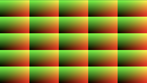
When you run the code, it won't look entirely like a grid, so let's multiply the uv variable by 5. so we can create a 5x5 grid.
const vec2 hexSide = vec2(1.7320508, 1); // proportion between two sides of 30-60-90 triangle

void mainImage( out vec4 fragColor, in vec2 fragCoord )
{
    vec3 col = vec3(0);

    vec2 uv = (fragCoord - iResolution.xy * .5)/iResolution.y;

    uv *= 5.;

    vec2 hc1 = floor(uv / hexSide) + .5;

    vec2 rg1 = vec2(uv - hc1 * hexSide);

    col = vec3(rg1, 0);

    fragColor = vec4(col,1.0);
}
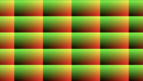
Next, we'll create a second set of hexagon center points and a second grid using those points.
const vec2 hexSide = vec2(1.7320508, 1); // proportion between two sides of 30-60-90 triangle

void mainImage( out vec4 fragColor, in vec2 fragCoord )
{
    vec3 col = vec3(0);

    vec2 uv = (fragCoord - iResolution.xy * .5)/iResolution.y;

    uv *= 5.;

    // hexagon center points
    vec2 hc1 = floor(uv / hexSide) + .5;
    vec2 hc2 = floor((uv - vec2(sqrt(3.)/2., .5)) / hexSide) + .5;

    // rectangular grids
    vec2 rg1 = vec2(uv - hc1 * hexSide);
    vec2 rg2 = vec2(uv - (hc2 + .5) * hexSide);

    col = vec3(rg2, 0);

    fragColor = vec4(col,1.0);
}
When this code is run, we see that this new grid is very similar to the first grid, but it has been shifted a bit. In fact, the second grid is offset by sqrt(3.)/2. along the x-axis and by 0.5 along the y-axis. Each cell of the second grid is effectively placed halfway between the edges of the first grid's cells.
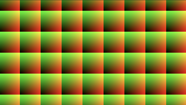
We can add up the two grids together to visualize how they overlap with each other.
const vec2 hexSide = vec2(1.7320508, 1); // proportion between two sides of 30-60-90 triangle

void mainImage( out vec4 fragColor, in vec2 fragCoord )
{
    vec3 col = vec3(0);

    vec2 uv = (fragCoord - iResolution.xy * .5)/iResolution.y;

    uv *= 5.;

    // hexagon center points
    vec2 hc1 = floor(uv / hexSide) + .5;
    vec2 hc2 = floor((uv - vec2(sqrt(3.)/2., .5)) / hexSide) + .5;

    // rectangular grids
    vec2 rg1 = vec2(uv - hc1 * hexSide);
    vec2 rg2 = vec2(uv - (hc2 + .5) * hexSide);

    // overlap of the two grids
    col = vec3(rg1 + rg2, 0);

    fragColor = vec4(col,1.0);
}
When the code is run, we see that we now have a 10x10 grid.
So...we made two rectangular grids? What about hexagons? The secret trick to making a hexagon grid system in shaders is to use two rectangular grids and find which grid a pixel is closest to. Let's see what I mean.
const vec2 hexSide = vec2(1.7320508, 1); // proportion between two sides of 30-60-90 triangle

void mainImage( out vec4 fragColor, in vec2 fragCoord )
{
    vec3 col = vec3(0);

    vec2 uv = (fragCoord - iResolution.xy * .5)/iResolution.y;

    uv *= 5.;

    // hexagon center points
    vec2 hc1 = floor(uv / hexSide) + .5;
    vec2 hc2 = floor((uv - vec2(sqrt(3.)/2., .5)) / hexSide) + .5;

    // rectangular grids
    vec2 rg1 = vec2(uv - hc1 * hexSide);
    vec2 rg2 = vec2(uv - (hc2 + .5) * hexSide);

    vec2 hexGrid = length(rg1) < length(rg2) ? rg1 : rg2;

    // this is the part where you drop your jaw in amazement
    col = vec3(hexGrid, 0);

    fragColor = vec4(col,1.0);
}
After running this code, we'll magically end up with a hexagon grid! Yay! 🎉
What a great feeling it is to see a hexagon grid sprout into existence in a fragment shader!
Are you scratching your head? I know I was when I first learned about this technique! How did we turn a group of two rectangular grids into hexagons? What wizardry is this?!
Let me explain using some illustrations. In the image below, we are drawing one grid cell from each grid we defined in our shader.
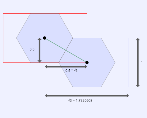
Each grid cell in our rectangular grids supports up to one hexagon. Due to how we constructed our UV coordinates, the max height of each hexagon is equal to one. Half the height of the hexagon is 0.5.
When we used the floor function in our code, we divided the uv coordinates by hexSide, equal to vec2(1.7320508, 1). This operation split our canvas into a rectangular grid where each cell has a width of 1.7320508 (the square root of 3) and a height of 1. Each grid is offset each other by half its width and height.
The hexagon center points are directly in the center of each grid cell. When the fragment shader runs for every pixel, we perform the following check:
vec2 hexGrid = length(rg1) < length(rg2) ? rg1 : rg2;
This is where the magic happens. We check the distance between each pixel and the center point of each rectangle. If the pixel is closer to rg1, the first grid, then we should choose to use that grid. If the pixel is closer to rg2, then we use the second grid. This causes a hexagon grid to materialize. We chose the width and height of each grid cell very carefully such that they were proportional to the legs of a 30-60-90 triangle.
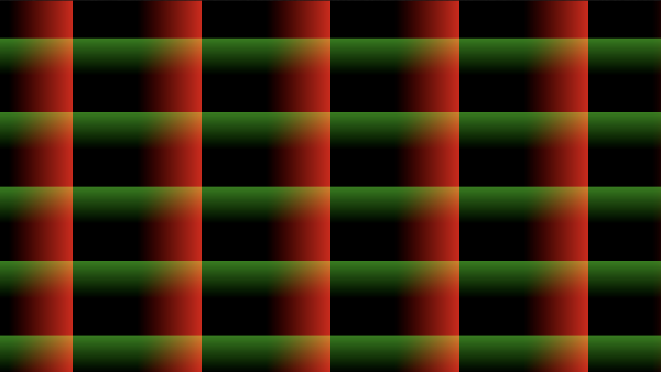
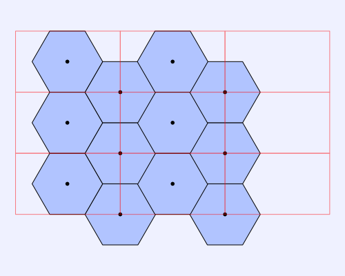
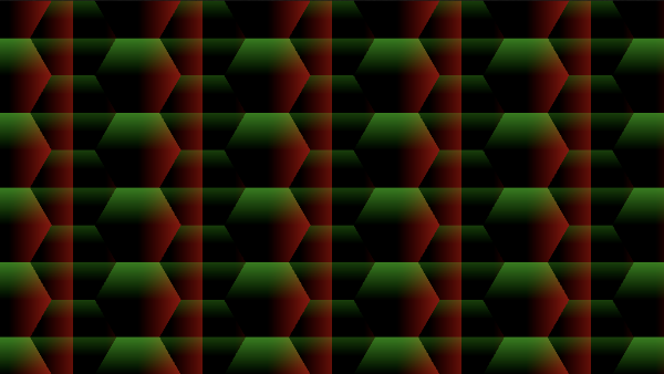
The image below represents how the hexagon grid looks like with the first rectangular grid overlaid on top.
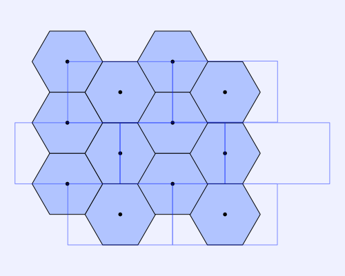
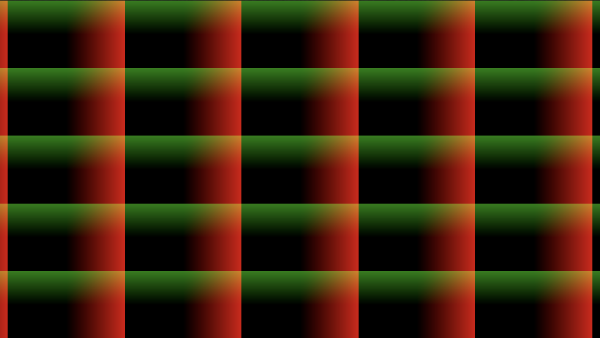
The next image represents how the hexagon grid looks like with the second rectangular grid overlaid.
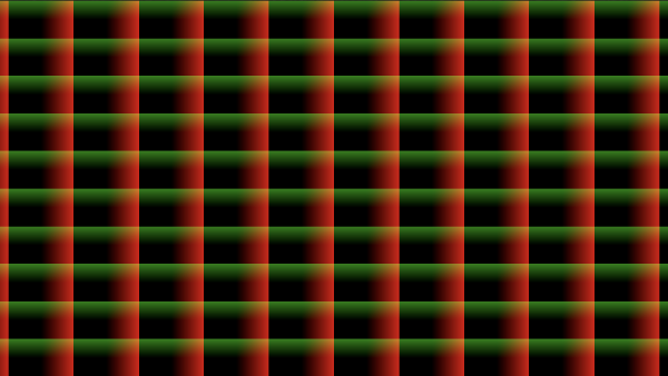
Next, we can look at the hexagon grid with both rectangular grids overlaid.
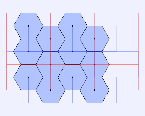
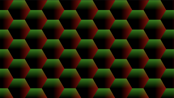
We can also see how the hexagon grid superimposes with the rectangular grids in our shader code.
const vec2 hexSide = vec2(1.7320508, 1); // proportion between two sides of 30-60-90 triangle

void mainImage( out vec4 fragColor, in vec2 fragCoord )
{
    vec3 col = vec3(0);

    vec2 uv = (fragCoord - iResolution.xy * .5)/iResolution.y;

    uv *= 5.;

    // hexagon center points
    vec2 hc1 = floor(uv / hexSide) + .5;
    vec2 hc2 = floor((uv - vec2(sqrt(3.)/2., .5)) / hexSide) + .5;

    // rectangular grids
    vec2 rg1 = vec2(uv - hc1 * hexSide);
    vec2 rg2 = vec2(uv - (hc2 + .5) * hexSide);

    vec2 hexGrid = length(rg1) < length(rg2) ? rg1 : rg2;

    // overlap the hexagon grid with the first rectangular grid
    col = vec3(hexGrid * 0.5 + rg1 * 0.5, 0);

    fragColor = vec4(col,1.0);
}
The brighter hexagons are the ones centered in each cell of the grid, rg1. The darker hexagons are centered in each cell of the grid, rg2.
Congrats! We made a hexagon coordinate system! We now have access to the UV coordinates of every hexagon in the canvas. That means we can do cool stuff like this:
const vec2 hexSide = vec2(1.7320508, 1); // proportion between two sides of 30-60-90 triangle
void mainImage( out vec4 fragColor, in vec2 fragCoord )
{
vec3 col = vec3(0);
vec2 uv = (fragCoord - iResolution.xy * .5)/iResolution.y;
uv *= 5.;
// hexagon center points
vec2 hc1 = floor(uv / hexSide) + .5;
vec2 hc2 = floor((uv - vec2(sqrt(3.)/2., .5)) / hexSide) + .5;
// rectangular grids
vec2 g1 = vec2(uv - hc1 * hexSide);
vec2 g2 = vec2(uv - (hc2 + .5) * hexSide);
vec2 hexGrid = length(g1) < length(g2) ? g1 : g2;
col = vec3(hexGrid, 0);
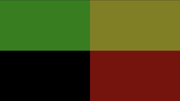
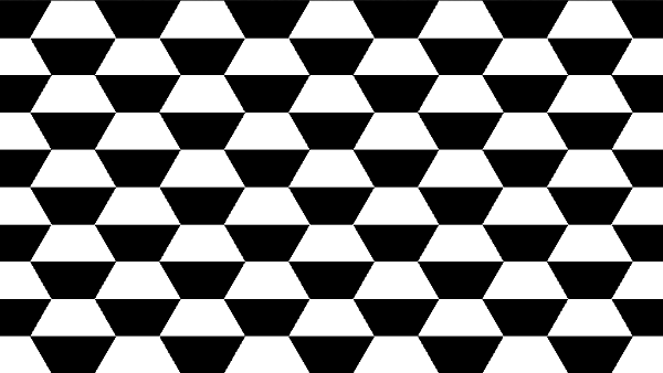
// hexagon UV coordinates range from -0.5 to 0.5 along y-axis,
// so change the color depending on if uv.y is greater or less
// than zero
if (hexGrid.y > 0.) col = vec3(1);
else col = vec3(0);
fragColor = vec4(col,1.0);
}
After compiling the shader code, we should see a cool black and white pattern where half of the hexagon is black, and the other half is white. Yin-yang hexagons! ☯
We can use our hexagonal coordinates to color every hexagon at the same time, but how do we target individual hexagons in a shader? That's where hexagon IDs come into play.
Hexagon IDs
When we were building our hexagon grid, we defined a hexagon center for each hexagon. We didn't know whether the hexagon would belong to the rectangular grid rg1 or grid rg2, so we made center points for both of them.
// hexagon center points
vec2 hc1 = floor(uv / hexSide) + .5;
vec2 hc2 = floor((uv - vec2(sqrt(3.)/2., .5)) / hexSide) + .5;
We can actually store the value of these IDs in the same vector used to store the hexagonal coordinates. That is, we can make hexGrid have a type of vec4 instead of vec2, so we can hold two more pieces of data.
vec4 hexGrid = length(g1) < length(g2)
        ? vec4(g1, hc1)
        : vec4(g2, hc2 + .5);
Now, the third and fourth components of hexGrid will contain the ID for each hexagon along the x-axis and y-axis, respectively.
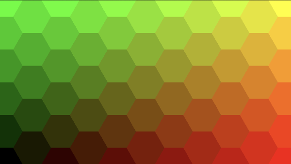
We can actually view these IDs in our shader by tweaking the color values into something that is between zero and one.
const vec2 hexSide = vec2(1.7320508, 1); // proportion between two sides of 30-60-90 triangle

void mainImage( out vec4 fragColor, in vec2 fragCoord )
{
    vec3 col = vec3(0);

    vec2 uv = (fragCoord - iResolution.xy * .5)/iResolution.y;

    uv *= 5.;

    // hexagon center points
    vec2 hc1 = floor(uv / hexSide) + .5;
    vec2 hc2 = floor((uv - vec2(sqrt(3.)/2., .5)) / hexSide) + .5;

    // rectangular grids
    vec2 g1 = vec2(uv - hc1 * hexSide);
    vec2 g2 = vec2(uv - (hc2 + .5) * hexSide);

    vec4 hexGrid = length(g1) < length(g2)
        ? vec4(g1, hc1)
        : vec4(g2, hc2 + .5);

    // tweak the color until every hexagon is visible
    col = vec3(hexGrid.zw * 0.2 + 0.5, 0);

    fragColor = vec4(col,1.0);
}
myVec, by using either myVec.zw or myVec.ba.When we run our shader code, we'll see that every hexagon has a unique color 🌈
Try adding a blue component to the color to see another cool effect.
col = vec3(hexGrid.zw * 0.2 + 0.5, 1);
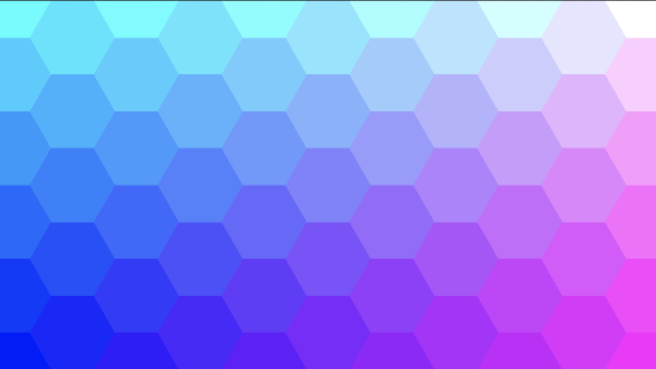
Notice how the colors change as you go from the bottom-left corner of the canvas to the ends of the x-axis and y-axis. Essentially, each hexagon's ID is a UV coordinate with an x-component and y-component that is the same no matter where you are in that particular hexagon.
We need to use IDs frequently in shaders that draw multiple shapes because every pixel is drawn to the screen at the same time using the GPU. It's not the same as when we drew shapes using the CPU via the 2D HTML canvas. Using IDs help us target specific hexagons, so we can color them differently, animate them differently, etc.
Code Cleanup
Let's move our logic for building a hexagon grid to a function called hexC (for hexagonal coordinates) because we will need to utilize it later when add interactivity and hover effects in the next tutorial.
vec4 hexC(vec2 p) {
    // hexagon center points
    vec2 hc1 = floor(p / hexSide) + .5;
    vec2 hc2 = floor((p - vec2(sqrt(3.)/2., .5)) / hexSide) + .5;

    // rectangular grids
    vec2 g1 = vec2(p - hc1 * hexSide);
    vec2 g2 = vec2(p - (hc2 + .5) * hexSide);

    // hexagonal coordinates and IDs
    return length(g1) < length(g2)
        ? vec4(g1, hc1)
        : vec4(g2, hc2 + .5);
}
We can actually simplify this code down a bit and improve performance by defining less variables and making less calculations.
For instance, we can simplify the following two lines of code:
vec2 hc1 = floor(p / hexSide) + .5;
vec2 hc2 = floor((p - vec2(sqrt(3.)/2., .5)) / hexSide) + .5;
Into a single line:
vec4 hc = floor(vec4(p, p - vec2(hexSide.x/2., .5)) / hexSide.xyxy) + .5;
Notice how we're using hexSide.x/2. instead of sqrt(3.)/2.. By avoiding sqrt, we're improving performance. We technically could have pre-computed hexSize.x/2. as well, but I'm keeping it in the code to help make the code more comprehensible.
In a similar fashion, we can simplify the two lines of code used for making the rectangular grids:
vec2 g1 = vec2(p - hc1 * hexSide);
vec2 g2 = vec2(p - (hc2 + .5) * hexSide);
Into a single line again:
vec4 rg = vec4(p - hc.xy * hexSide, p - (hc.zw + .5) * hexSide);
Then, we can change the returned value by replacing this code:
return length(g1) < length(g2)
        ? vec4(g1, hc1)
        : vec4(g2, hc2 + .5);
With the following:
return length(rg.xy, rg.xy) < length(rg.zw, rg.zw)
        ? vec4(rg.xy, hc.xy)
        : vec4(rg.zw, hc.zw + .5);
We can also improve performance a bit by comparing the dot product between a grid's vector and itself instead of using the builtin length function. It's much faster to multiply vectors by themselves than to take the square root of the square of each vector's components. The comparison between the two grids will behave the same whether we use the length or dot function.
return dot(rg.xy, rg.xy) < dot(rg.zw, rg.zw)
        ? vec4(rg.xy, hc.xy)
        : vec4(rg.zw, hc.zw + .5);
After making the code adjustments, our hexC function should look like the following:
// hexagonal coordinates
vec4 hexC(vec2 p)
{
    // hexagon centers
    vec4 hc = floor(vec4(p, p - vec2(hexSide.x/2., .5)) / hexSide.xyxy) + .5;

    // rectangular grids
    vec4 rg = vec4(p - hc.xy * hexSide, p - (hc.zw + .5) * hexSide);

    // hexagonal grid and IDs
    return dot(rg.xy, rg.xy) < dot(rg.zw, rg.zw)
        ? vec4(rg.xy, hc.xy)
        : vec4(rg.zw, hc.zw + .5);
}
We can add the hexD function we implemented in the previous tutorial to our code as well.
// hexagonal distance
float hexD(in vec2 p)
{
    p = abs(p);

    return max(dot(p, hexSide * .5), p.y);
}
Finished Code
With our code cleaned up, our final code should look like the following.
const vec2 hexSide = vec2(1.7320508, 1); // proportion between two sides of 30-60-90 triangle

// hexagonal distance
float hexD(in vec2 p)
{
    p = abs(p);

    return max(dot(p, hexSide * .5), p.y);
}

// hexagonal coordinates
vec4 hexC(vec2 p)
{
    // hexagon centers
    vec4 hc = floor(vec4(p, p - vec2(hexSide.x/2., .5)) / hexSide.xyxy) + .5;

    // rectangular grids
    vec4 rg = vec4(p - hc.xy * hexSide, p - (hc.zw + .5) * hexSide);

    // hexagonal grid and IDs
    return dot(rg.xy, rg.xy) < dot(rg.zw, rg.zw)
        ? vec4(rg.xy, hc.xy)
        : vec4(rg.zw, hc.zw + .5);
}

void mainImage( out vec4 fragColor, in vec2 fragCoord )
{
    vec3 col = vec3(0);

    vec2 uv = (fragCoord - iResolution.xy * .5)/iResolution.y;

    uv *= 5.;

    vec4 h = hexC(uv);

    col = vec3(h.zw * 0.2 + 0.5, 1);

    fragColor = vec4(col,1.0);
}
Conclusion
In this tutorial, we learned how to use math magic to create a hexagon grid inside a fragment shader. We created a new function that accepts Cartesian coordinates and returns our custom-made hexagonal coordinates. We also learned how to create IDs for each hexagon in the grid, so we can target any hexagon we want.
In the next tutorial, we'll add cool hover effects and color transitions to our hexagon grid, similar to what we learned in Part 2 of this tutorial series. Learning how to program shaders is a lot different than using JavaScript and the HTML canvas API, huh?
If you've enjoyed this series so far, why not put the "Nate" in donate? Yes, my nickname is Nate, and I make terrible puns 😅
All money goes toward keeping my website running and fueling my passion to make more amazing tutorial series like this one 🙂