Shadertoy Tutorial Part 9 - Camera Movement
Greetings, friends! It's April Fools' day! I hope you don't fall for many pranks today! 😂 Welcome to Part 9 of my Shadertoy tutorial series. In this tutorial, we'll learn how move the camera around the scene.
Initial Setup
Let's create a new shader and add the following boilerplate code.
// Rotation matrix around the X axis.
mat3 rotateX(float theta) {
    float c = cos(theta);
    float s = sin(theta);
    return mat3(
        vec3(1, 0, 0),
        vec3(0, c, -s),
        vec3(0, s, c)
    );
}

// Rotation matrix around the Y axis.
mat3 rotateY(float theta) {
    float c = cos(theta);
    float s = sin(theta);
    return mat3(
        vec3(c, 0, s),
        vec3(0, 1, 0),
        vec3(-s, 0, c)
    );
}

// Rotation matrix around the Z axis.
mat3 rotateZ(float theta) {
    float c = cos(theta);
    float s = sin(theta);
    return mat3(
        vec3(c, -s, 0),
        vec3(s, c, 0),
        vec3(0, 0, 1)
    );
}

// Identity matrix.
mat3 identity() {
    return mat3(
        vec3(1, 0, 0),
        vec3(0, 1, 0),
        vec3(0, 0, 1)
    );
}

const int MAX_MARCHING_STEPS = 255;
const float MIN_DIST = 0.0;
const float MAX_DIST = 100.0;
const float PRECISION = 0.001;

struct Surface {
    float sd; // signed distance value
    vec3 col; // color
};

Surface sdBox( vec3 p, vec3 b, vec3 offset, vec3 col, mat3 transform)
{
  p = (p - offset) * transform; // apply transformation matrix
  vec3 q = abs(p) - b;
  float d = length(max(q,0.0)) + min(max(q.x,max(q.y,q.z)),0.0);
  return Surface(d, col);
}

Surface sdFloor(vec3 p, vec3 col) {
  float d = p.y + 1.;
  return Surface(d, col);
}

Surface minWithColor(Surface obj1, Surface obj2) {
  if (obj2.sd < obj1.sd) return obj2;
  return obj1;
}

Surface sdScene(vec3 p) {
  vec3 floorColor = vec3(1. + 0.7*mod(floor(p.x) + floor(p.z), 2.0));
  Surface co = sdFloor(p, floorColor);
  co = minWithColor(co, sdBox(p, vec3(1), vec3(0, 0.5, -4), vec3(1, 0, 0), identity()));
  return co;
}

Surface rayMarch(vec3 ro, vec3 rd, float start, float end) {
  float depth = start;
  Surface co; // closest object

  for (int i = 0; i < MAX_MARCHING_STEPS; i++) {
    vec3 p = ro + depth * rd;
    co = sdScene(p);
    depth += co.sd;
    if (co.sd < PRECISION || depth > end) break;
  }

  co.sd = depth;

  return co;
}

vec3 calcNormal(in vec3 p) {
    vec2 e = vec2(1.0, -1.0) * 0.0005; // epsilon
    return normalize(
      e.xyy * sdScene(p + e.xyy).sd +
      e.yyx * sdScene(p + e.yyx).sd +
      e.yxy * sdScene(p + e.yxy).sd +
      e.xxx * sdScene(p + e.xxx).sd);
}

void mainImage( out vec4 fragColor, in vec2 fragCoord )
{
  vec2 uv = (fragCoord-.5*iResolution.xy)/iResolution.y;
  vec3 backgroundColor = vec3(0.835, 1, 1);

  vec3 col = vec3(0);
  vec3 ro = vec3(0, 0, 3); // ray origin that represents camera position
  vec3 rd = normalize(vec3(uv, -1)); // ray direction

  Surface co = rayMarch(ro, rd, MIN_DIST, MAX_DIST); // closest object

  if (co.sd > MAX_DIST) {
    col = backgroundColor; // ray didn't hit anything
  } else {
    vec3 p = ro + rd * co.sd; // point on cube or floor we discovered from ray marching
    vec3 normal = calcNormal(p);
    vec3 lightPosition = vec3(2, 2, 7);
    vec3 lightDirection = normalize(lightPosition - p);

    float dif = clamp(dot(normal, lightDirection), 0.3, 1.); // diffuse reflection

    col = dif * co.col + backgroundColor * .2; // Add a bit of background color to the diffuse color
  }

  // Output to screen
  fragColor = vec4(col, 1.0);
}
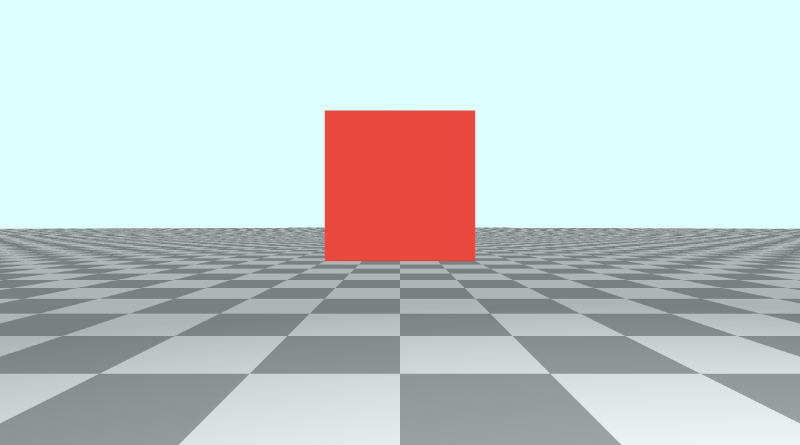
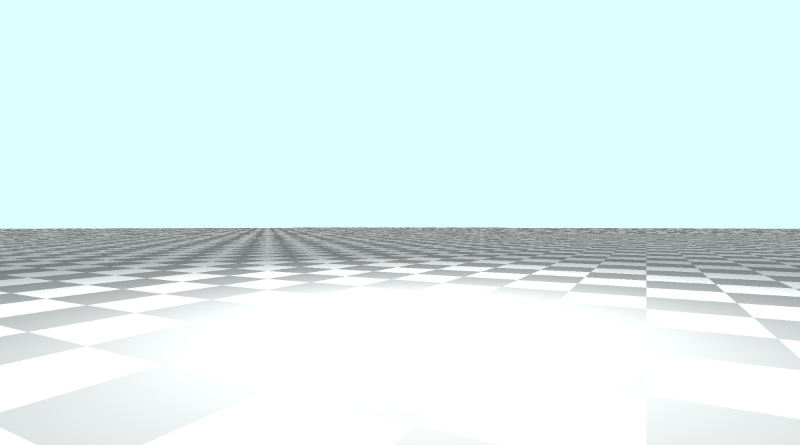
This code creates a scene with a tiled floor, sky (background color), and a red cube. It also contains the rotation matrices we learned about in the last tutorial.
Panning the Camera
Panning the camera is actually very basic. The camera is currently pointing toward a cube that is floating slightly in the air a certain distance from the camera along the z-axis. Since our coordinate system uses the right-hand rule, the z-axis is negative when it goes away from the camera and positive when it comes toward the camera.
Our camera is sitting at a position defined by the variable, ro, which is the ray origin. Currently, it's set equal to vec3(0, 0, 3). To pan the camera along the x-direction, we simply adjust the x-component of ro.
vec3 ro = vec3(1, 0, 3);
Our camera has now shifted to the right, which creates the effect of moving the cube to the left.
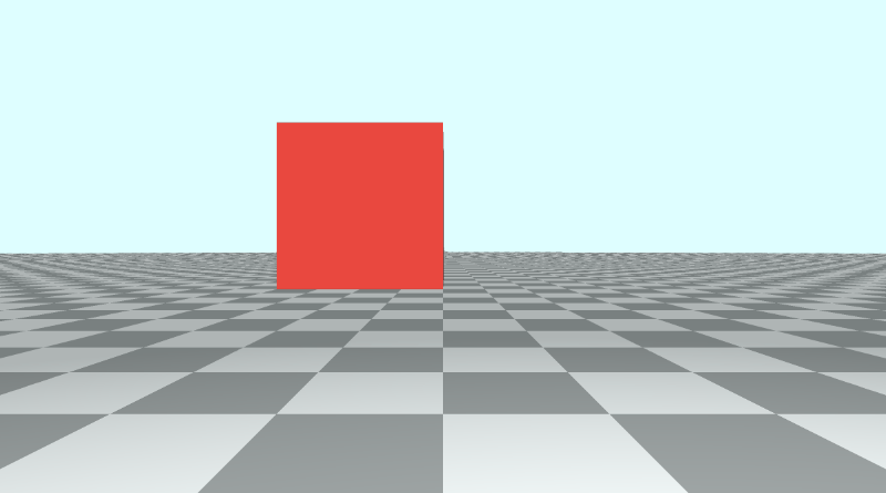
Likewise, we can adjust the y-component of ro to move the camera up or down.
vec3 ro = vec3(0, 1, 3);
Moving the camera up has the effect of moving the cube and floor down.
You can pan the camera along a circular path by using cos and sin functions along the x-axis and y-axis, respectively.
vec3 ro = vec3(cos(iTime), sin(iTime) + 0.1, 3);
Obviously, it starts looking strange as you dip into the floor a bit, so I added 0.1 to the y-component to prevent flashing effects that may occur.
Tilting/Rotating the Camera
Suppose we want to keep the camera position, ro, the same, but we want to tilt the camera up, down, left, or right. Maybe we want to even turn the camera all the way around such that the camera turns around at a 180 degree angle. This involves applying a transformation matrix to the ray direction, rd.
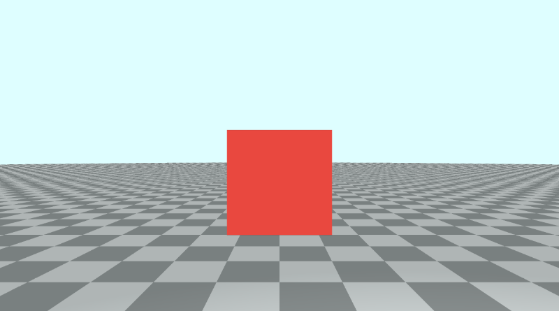
Let's set the ray origin back to normal:
vec3 ro = vec3(0, 0, 3);
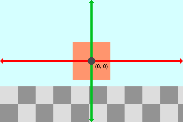
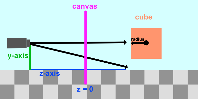
The cube should look centered on the canvas now. Currently, our scene from a side view is similar to the following illustration:
We want to keep the camera position the same but be able to tilt it in any direction. Suppose we wanted to tilt the camera upwards. Our scene would be similar to the following illustration:
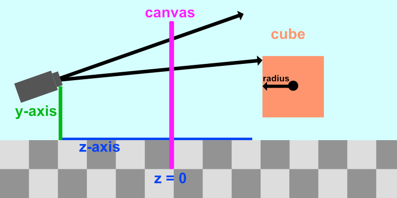
Notice how the rays being shot out of the camera have tilted upwards too. To tilt the camera means tilting all of the rays being fired out of the camera.
Tilting the camera is similar to the aircraft principal axes.
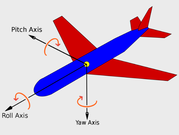
The camera can not only pan along the x-axis, y-axis, or z-axis, but it can also tilt (or rotate) along three rotational axes: pitch, yaw, and roll. This means the camera has six degrees of freedom: three positional axes and three rotational axes.
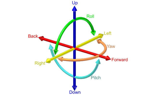
Luckily for us, we can use the same rotation matrices we used in the last tutorial to apply pitch, yaw, and roll.
"Pitch" is applied using the rotateX function, "yaw" is applied using the rotateY function, and "roll" is applied using the rotateZ function.
If we want to tilt the camera up/down, or apply "pitch," then we need to apply the rotateX function to the ray direction, rd.
vec3 rd = normalize(vec3(uv, -1));
rd *= rotateX(0.3);
We simply multiply the ray direction by one or more rotation matrices to tilt the camera. That will tilt the direction of every ray fired from the camera, changing the view we see in the Shadertoy canvas.
Let's animate the tilt such that the "pitch" angle oscillates between -0.5 and 0.5.
vec3 rd = normalize(vec3(uv, -1));
rd *= rotateX(sin(iTime) * 0.5);
To tilt the camera left/right, or apply "yaw", we need to apply the rotateY function.
vec3 rd = normalize(vec3(uv, -1));
rd *= rotateY(sin(iTime) * 0.5);
To tilt the camera from side to side, or apply "roll", we need to apply the rotateZ function. Do a barrel roll! 🐰
vec3 rd = normalize(vec3(uv, -1));
rd *= rotateZ(sin(iTime) * 0.5);
Rotating the Camera a Full 360
We can also apply yaw between negative pi and positive pi to spin the scene around a complete 360 degree angle.
const float PI = 3.14159265359;
vec3 rd = normalize(vec3(uv, -1));
rd *= rotateY(sin(iTime * 0.5) * PI); // 0.5 is used to slow the animation down
When you look behind the camera, you'll likely find a glowy spot on the ground. This glowy spot is the position of the light, currently set up at vec3(2, 2, 7). Since the positive z-axis is setup to be behind the camera typically, you end up seeing the light when you turn the camera around.
You make think the glowy spot is an April Fools' joke, but it's actually a result of the diffuse reflection calculation from Part 6.
float dif = clamp(dot(normal, lightDirection), 0.3, 1.);
col = dif * co.col + backgroundColor * .2;
Since we're coloring the floor based on the diffuse reflection and the surface normal, the floor appears brightest where the light position is located. If you want to remove this sunspot, you'll have to remove the floor from the lighting calculations.
Typically, this shouldn't be an issue since the light is behind the camera. If you want to have scenes with a floor where the camera turns around, then you'll probably want to remove the glowy spot.
Once approach to removing this "sun spot" or "sun glare" as I like to call it is to assign an ID to each object in the scene. Then, you can remove the floor from the lighting calculation by checking if the floor is the closest object in the scene after performing ray marching.
// Rotation matrix around the X axis.
mat3 rotateX(float theta) {
    float c = cos(theta);
    float s = sin(theta);
    return mat3(
        vec3(1, 0, 0),
        vec3(0, c, -s),
        vec3(0, s, c)
    );
}

// Rotation matrix around the Y axis.
mat3 rotateY(float theta) {
    float c = cos(theta);
    float s = sin(theta);
    return mat3(
        vec3(c, 0, s),
        vec3(0, 1, 0),
        vec3(-s, 0, c)
    );
}

// Rotation matrix around the Z axis.
mat3 rotateZ(float theta) {
    float c = cos(theta);
    float s = sin(theta);
    return mat3(
        vec3(c, -s, 0),
        vec3(s, c, 0),
        vec3(0, 0, 1)
    );
}

// Identity matrix.
mat3 identity() {
    return mat3(
        vec3(1, 0, 0),
        vec3(0, 1, 0),
        vec3(0, 0, 1)
    );
}

const int MAX_MARCHING_STEPS = 255;
const float MIN_DIST = 0.0;
const float MAX_DIST = 100.0;
const float PRECISION = 0.001;

struct Surface {
    float sd; // signed distance value
    vec3 col; // color
    int id; // identifier for each surface/object
};

/*
Surface IDs:
1. Floor
2. Box
*/

Surface sdBox( vec3 p, vec3 b, vec3 offset, vec3 col, mat3 transform)
{
  p = (p - offset) * transform;
  vec3 q = abs(p) - b;
  float d = length(max(q,0.0)) + min(max(q.x,max(q.y,q.z)),0.0);
  return Surface(d, col, 2);
}

Surface sdFloor(vec3 p, vec3 col) {
  float d = p.y + 1.;
  return Surface(d, col, 1);
}

Surface minWithColor(Surface obj1, Surface obj2) {
  if (obj2.sd < obj1.sd) return obj2;
  return obj1;
}

Surface sdScene(vec3 p) {
  vec3 floorColor = vec3(.5 + 0.3*mod(floor(p.x) + floor(p.z), 2.0));
  Surface co = sdFloor(p, floorColor);
  co = minWithColor(co, sdBox(p, vec3(1), vec3(0, 0.5, -4), vec3(1, 0, 0), identity()));
  return co;
}

Surface rayMarch(vec3 ro, vec3 rd, float start, float end) {
  float depth = start;
  Surface co; // closest object

  for (int i = 0; i < MAX_MARCHING_STEPS; i++) {
    vec3 p = ro + depth * rd;
    co = sdScene(p);
    depth += co.sd;
    if (co.sd < PRECISION || depth > end) break;
  }

  co.sd = depth;

  return co;
}

vec3 calcNormal(in vec3 p) {
    vec2 e = vec2(1.0, -1.0) * 0.0005; // epsilon
    return normalize(
      e.xyy * sdScene(p + e.xyy).sd +
      e.yyx * sdScene(p + e.yyx).sd +
      e.yxy * sdScene(p + e.yxy).sd +
      e.xxx * sdScene(p + e.xxx).sd);
}

void mainImage( out vec4 fragColor, in vec2 fragCoord )
{
  vec2 uv = (fragCoord-.5*iResolution.xy)/iResolution.y;
  vec3 backgroundColor = vec3(0.835, 1, 1);

  vec3 col = vec3(0);
  vec3 ro = vec3(0, 0, 3); // ray origin that represents camera position

  const float PI = 3.14159265359;
  vec3 rd = normalize(vec3(uv, -1));
  rd *= rotateY(sin(iTime * 0.5) * PI); // 0.5 is used to slow the animation down

  Surface co = rayMarch(ro, rd, MIN_DIST, MAX_DIST); // closest object

  if (co.sd > MAX_DIST) {
    col = backgroundColor; // ray didn't hit anything
  } else {
    vec3 p = ro + rd * co.sd; // point on cube or floor we discovered from ray marching
    vec3 normal = calcNormal(p);

    // check material ID
    if( co.id == 1 ) // floor
    {
        col = co.col;
    } else {
      // lighting
      vec3 lightPosition = vec3(2, 2, 7);
      vec3 lightDirection = normalize(lightPosition - p);

      // color
      float dif = clamp(dot(normal, lightDirection), 0.3, 1.); // diffuse reflection
      col = dif * co.col + backgroundColor * .2; // Add a bit of background color to the diffuse color
    }
  }

  // Output to screen
  fragColor = vec4(col, 1.0);
}
With this approach, the floor lighting will look a bit different, but the sun spot will be gone!
By assigning IDs to each surface, material, or object, we can keep track of which object was hit by a ray after ray marching is performed. This can be useful for applying lighting or coloring calculations that are unique to one or more objects.
Understanding iMouse
Shadertoy provides a set of global variables that you can use in your shader code to make it more interactive. If you open a new shader and click on the arrow next to "Shader inputs," then you'll see a list of global variables.
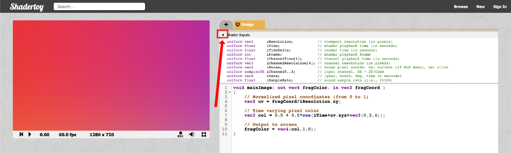
Below is a list of global variables you can use in Shadertoy shaders.
Shader Inputs
uniform vec3      iResolution;           // viewport resolution (in pixels)
uniform float     iTime;                 // shader playback time (in seconds)
uniform float     iTimeDelta;            // render time (in seconds)
uniform int       iFrame;                // shader playback frame
uniform float     iChannelTime[4];       // channel playback time (in seconds)
uniform vec3      iChannelResolution[4]; // channel resolution (in pixels)
uniform vec4      iMouse;                // mouse pixel coords. xy: current (if MLB down), zw: click
uniform samplerXX iChannel0..3;          // input channel. XX = 2D/Cube
uniform vec4      iDate;                 // (year, month, day, time in seconds)
uniform float     iSampleRate;           // sound sample rate (i.e., 44100)
Among them, you'll see a variable called iMouse that can be used to get the position of your mouse as you click somewhere on the canvas. This variable is of type vec4 and therefore contains four pieces of information about a left mouse click.
vec4 mouse = iMouse;

mouse.xy = mouse position during last button down
abs(mouse.zw) = mouse position during last button click
sign(mouze.z) = button is down (positive if down)
sign(mouze.w) = button is clicked (positive if clicked)
A mouse click is what happens immediately after you press the mouse. A mouse down event is what happens after you continue holding it down.
This tutorial by Inigo Quilez, one of the co-creators of Shadertoy, shows you how to use each piece of data stored in iMouse. When you click anywhere in the scene, a white circle appears when you perform a mouse click. If you continue holding the mouse down and move the mouse around, a yellow line will appear between two circles. Once you release the mouse, the yellow line will disappear.
What we really care about for the purpose of this tutorial are the mouse coordinates. I made a small demo to show how you can move a circle around in the canvas using your mouse. Let's look at the code:
float sdfCircle(vec2 uv, float r, vec2 offset) {
  float x = uv.x - offset.x;
  float y = uv.y - offset.y;

  float d = length(vec2(x, y)) - r;

  return step(0., -d);
}

vec3 drawScene(vec2 uv, vec2 mp) {
  vec3 col = vec3(0);
  float blueCircle = sdfCircle(uv, 0.1, mp);
  col = mix(col, vec3(0, 1, 1), blueCircle);

  return col;
}

void mainImage( out vec4 fragColor, in vec2 fragCoord )
{
  vec2 uv = fragCoord/iResolution.xy - 0.5; // <-0.5,0.5>
  uv.x *= iResolution.x/iResolution.y; // fix aspect ratio

  // mp = mouse position of the last click
  vec2 mp = iMouse.xy/iResolution.xy - 0.5; // <-0.5,0.5>
  mp.x *= iResolution.x/iResolution.y; // fix aspect ratio

  vec3 col = drawScene(uv, mp);

  // Output to screen
  fragColor = vec4(col,1.0);
}
Notice how getting the mouse position is very similar to the UV coordinates. We can normalize the coordinates through the following statement:
vec2 mp = iMouse.xy/iResolution.xy // range is between 0 and 1
This will normalize the mouse coordinates to be between zero and one. By subtracting 0.5, we can normalize the mouse coordinates to be between -0.5 and 0.5.
vec2 mp = iMouse.xy/iResolution.xy - 0.5 // range is between -0.5 and 0.5
Panning the Camera with the Mouse
Now that we understand how to use the iMouse global variable, let's apply it to our camera. We can use the mouse to control panning by changing the value of the ray origin, ro.
vec2 mouse = iMouse.xy / iResolution.xy - 0.5; // <-0.5,0.5>
vec3 ro = vec3(mouse.x, mouse.y, 3); // ray origin will move as you click on the canvas and drag the mouse
If you click on the canvas and drag your mouse, you'll be able to pan the camera between -0.5 and 0.5 on both the x-axis and y-axis. The center of the canvas will be the point, (0, 0), which should move the cube back in the center of the canvas.
If you want to pan more, you can always multiply the mouse position values by a multiplier.
vec2 mouse = iMouse.xy / iResolution.xy - 0.5; // <-0.5,0.5>
vec3 ro = vec3(2. * mouse.x, 2. * mouse.y, 3);
Tilting/Rotating the Camera with the Mouse
We can tilt/rotate the camera with the mouse by changing the value of theta, the angle we supply to our rotation matrices such as rotateX, rotateY, and rotateZ. Make sure that you're no longer using the mouse to control the ray origin, ro. Otherwise, you may end up with a very strange camera.
Let's apply "yaw" to the ray direction to tilt the camera left to right.
vec2 mouse = iMouse.xy / iResolution.xy - 0.5; // <-0.5,0.5>
vec3 rd = normalize(vec3(uv, -1)); // ray direction
rd *= rotateY(mouse.x); // apply yaw
Since mouse.x is currently constrained between -0.5 and 0.5, it might make more sense to remap this range to something like negative pi (-π) to positive pi (+π). To remap a range to a new range, we can make use of the mix function. It's already built to handle linear interpolation, so it's perfect for remapping values from one range to another.
Let's remap the range, <-0.5, 0.5>, to <-π, π>.
vec2 mouse = iMouse.xy / iResolution.xy - 0.5; // <-0.5,0.5>
vec3 rd = normalize(vec3(uv, -1)); // ray direction
rd *= rotateY(mix(-PI, PI, mouse.x)); // apply yaw with a 360 degree range
Now, we can make a complete 360 rotation using our mouse!
You may be wondering how we can use the mouse.y value. We can use this value to tilt the camera up and down as the "pitch" angle. That means we need to leverage the rotateX function.
vec2 mouse = iMouse.xy / iResolution.xy - 0.5; // <-0.5,0.5>
vec3 rd = normalize(vec3(uv, -1)); // ray direction
rd *= rotateX(mouse.y); // apply pitch
This will let us tilt the camera up and down between the values of -0.5 and 0.5.
If you want to use the mouse to change the "yaw" angle with mouse.x and "pitch" with mouse.y simultaneously, then we need to multiply the rotation matrices together.
vec2 mouse = iMouse.xy / iResolution.xy - 0.5; // <-0.5,0.5>
vec3 rd = normalize(vec3(uv, -1));
rd *= rotateY(mouse.x) * rotateX(mouse.y); // apply yaw and pitch
Now, you can freely tilt the camera with your mouse to look around the scene! This can be handy for troubleshooting complex 3D scenes built with Shadertoy. In software such as Unity or Blender, you already have a powerful camera you can use to look around 3D scenes.
You can find the finished code below:
// Rotation matrix around the X axis.
mat3 rotateX(float theta) {
    float c = cos(theta);
    float s = sin(theta);
    return mat3(
        vec3(1, 0, 0),
        vec3(0, c, -s),
        vec3(0, s, c)
    );
}

// Rotation matrix around the Y axis.
mat3 rotateY(float theta) {
    float c = cos(theta);
    float s = sin(theta);
    return mat3(
        vec3(c, 0, s),
        vec3(0, 1, 0),
        vec3(-s, 0, c)
    );
}

// Rotation matrix around the Z axis.
mat3 rotateZ(float theta) {
    float c = cos(theta);
    float s = sin(theta);
    return mat3(
        vec3(c, -s, 0),
        vec3(s, c, 0),
        vec3(0, 0, 1)
    );
}

// Identity matrix.
mat3 identity() {
    return mat3(
        vec3(1, 0, 0),
        vec3(0, 1, 0),
        vec3(0, 0, 1)
    );
}

const int MAX_MARCHING_STEPS = 255;
const float MIN_DIST = 0.0;
const float MAX_DIST = 100.0;
const float PRECISION = 0.001;

struct Surface {
    float sd; // signed distance value
    vec3 col; // color
    int id; // identifier for each surface/object
};

/*
Surface IDs:
1. Floor
2. Box
*/

Surface sdBox( vec3 p, vec3 b, vec3 offset, vec3 col, mat3 transform)
{
  p = (p - offset) * transform;
  vec3 q = abs(p) - b;
  float d = length(max(q,0.0)) + min(max(q.x,max(q.y,q.z)),0.0);
  return Surface(d, col, 2);
}

Surface sdFloor(vec3 p, vec3 col) {
  float d = p.y + 1.;
  return Surface(d, col, 1);
}

Surface minWithColor(Surface obj1, Surface obj2) {
  if (obj2.sd < obj1.sd) return obj2;
  return obj1;
}

Surface sdScene(vec3 p) {
  vec3 floorColor = vec3(.5 + 0.3*mod(floor(p.x) + floor(p.z), 2.0));
  Surface co = sdFloor(p, floorColor);
  co = minWithColor(co, sdBox(p, vec3(1), vec3(0, 0.5, -4), vec3(1, 0, 0), identity()));
  return co;
}

Surface rayMarch(vec3 ro, vec3 rd, float start, float end) {
  float depth = start;
  Surface co; // closest object

  for (int i = 0; i < MAX_MARCHING_STEPS; i++) {
    vec3 p = ro + depth * rd;
    co = sdScene(p);
    depth += co.sd;
    if (co.sd < PRECISION || depth > end) break;
  }

  co.sd = depth;

  return co;
}

vec3 calcNormal(in vec3 p) {
    vec2 e = vec2(1.0, -1.0) * 0.0005; // epsilon
    return normalize(
      e.xyy * sdScene(p + e.xyy).sd +
      e.yyx * sdScene(p + e.yyx).sd +
      e.yxy * sdScene(p + e.yxy).sd +
      e.xxx * sdScene(p + e.xxx).sd);
}

void mainImage( out vec4 fragColor, in vec2 fragCoord )
{
  vec2 uv = (fragCoord-.5*iResolution.xy)/iResolution.y;
  vec3 backgroundColor = vec3(0.835, 1, 1);

  vec3 col = vec3(0);
  vec3 ro = vec3(0, 0, 3); // ray origin that represents camera position

  vec2 mouse = iMouse.xy / iResolution.xy - 0.5; // <-0.5,0.5>
  vec3 rd = normalize(vec3(uv, -1)); // ray direction
  rd *= rotateY(mouse.x) * rotateX(mouse.y); // apply yaw and pitch

  Surface co = rayMarch(ro, rd, MIN_DIST, MAX_DIST); // closest object

  if (co.sd > MAX_DIST) {
    col = backgroundColor; // ray didn't hit anything
  } else {
    vec3 p = ro + rd * co.sd; // point on cube or floor we discovered from ray marching
    vec3 normal = calcNormal(p);

    // check material ID
    if( co.id == 1 ) // floor
    {
        col = co.col;
    } else {
      // lighting
      vec3 lightPosition = vec3(2, 2, 7);
      vec3 lightDirection = normalize(lightPosition - p);

      // color
      float dif = clamp(dot(normal, lightDirection), 0.3, 1.); // diffuse reflection
      col = dif * co.col + backgroundColor * .2; // Add a bit of background color to the diffuse color
    }
  }

  // Output to screen
  fragColor = vec4(col, 1.0);
}
Conclusion
In this tutorial, we learned how to move the camera in six degrees of freedom. We learned how to pan the camera around along the x-axis, y-axis, and z-axis. We also learned how to use rotation matrices to apply yaw, pitch, and roll, so we can control the camera's tilt. Using the knowledge you've learned today, you can debug 3D scenes in Shadertoy and make interesting animations.