Shadertoy Tutorial Part 16 - Cubemaps and Reflections
Greetings, friends! Welcome to Part 16 of my Shadertoy tutorial series! In this tutorial, I'll discuss how to use cubemaps in Shadertoy, so we can use draw 3D backgrounds and make more realistic reflections on any 3D object!
Cubemaps
Cubemaps are a special type of texture that can be thought of containing six individual 2D textures that each form a face of a cube. You may have used cubemaps in game engines such as Unity and Unreal Engine. In Shadertoy, cubemaps let you create a dynamic 3D background that changes depending on where the camera is facing. Each pixel of the Shadertoy canvas will be determined by the ray direction.
The website, Learn OpenGL, provides a great image to visualize how cubemaps work.
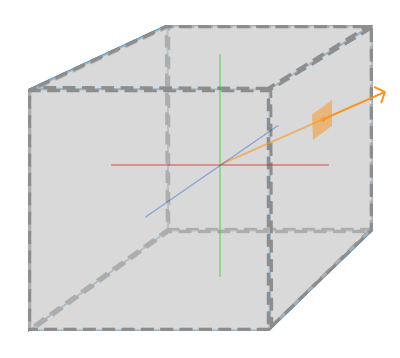
We pretend the camera is in the center of the cube and points toward one or more faces of the cube. In the image above, the ray direction determines which part of the cubemap to sample from.
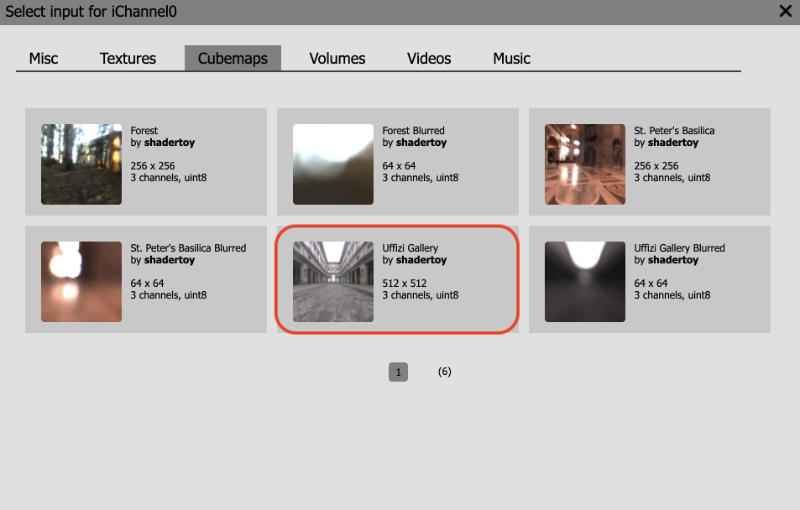
Let's practice this in Shadertoy. Create a new shader and click on the iChannel0 box. Click on the "Cubemaps" tab and select the "Uffizi Gallery" cubemap.
Then, replace all the code with the following:
const float PI = 3.14159265359;

mat2 rotate2d(float theta) {
  float s = sin(theta), c = cos(theta);
  return mat2(c, -s, s, c);
}

mat3 camera(vec3 cameraPos, vec3 lookAtPoint) {
    vec3 cd = normalize(lookAtPoint - cameraPos);
    vec3 cr = normalize(cross(vec3(0, 1, 0), cd));
    vec3 cu = normalize(cross(cd, cr));

    return mat3(-cr, cu, -cd);
}

void mainImage( out vec4 fragColor, in vec2 fragCoord )
{
  vec2 uv = (fragCoord-.5*iResolution.xy)/iResolution.y;
  vec2 mouseUV = iMouse.xy/iResolution.xy;
  if (mouseUV == vec2(0.0)) mouseUV = vec2(0.5); // trick to center mouse on page load

  vec3 lp = vec3(0);
  vec3 ro = vec3(0, 0, 3);
  ro.yz *= rotate2d(mix(-PI/2., PI/2., mouseUV.y));
  ro.xz *= rotate2d(mix(-PI, PI, mouseUV.x));

  vec3 rd = camera(ro, lp) * normalize(vec3(uv, -1));

  vec3 col = texture(iChannel0, rd).rgb;

  fragColor = vec4(col, 1.0);
}
Does this code look familiar? I took part of the code we used at the beginning of Part 14 of my Shadertoy tutorial series for this tutorial. We use the lookat camera model to adjust the ray direction, rd.
The color of each pixel, col, will be equal to a color value sampled from the cubemap stored in iChannel0. We learned how to access textures in the previous tutorial. However, accessing values from a cubemap requires us to pass in the ray direction, rd, instead of uv coordinates like what we did for 2D textures.
vec3 col = texture(iChannel0, rd).rgb;
You can use the mouse to look around the cubemap because we're using the iMouse global variable to control the ray origin, ro, which is the position of the camera. The camera function changes based on ro and lp, so the ray direction is changing as we move the mouse around. Looks like the background is a dynamic 3D scene now!
Reflections with Cubemap
Using cubemaps, we can make objects look reflective. Let's add a sphere to the scene using ray marching.
Replace your code with the following:
const int MAX_MARCHING_STEPS = 255;
const float MIN_DIST = 0.0;
const float MAX_DIST = 100.0;
const float PRECISION = 0.001;
const float EPSILON = 0.0005;
const float PI = 3.14159265359;

mat2 rotate2d(float theta) {
  float s = sin(theta), c = cos(theta);
  return mat2(c, -s, s, c);
}

float sdSphere(vec3 p, float r )
{
  return length(p) - r;
}

float sdScene(vec3 p) {
  return sdSphere(p, 1.);
}

float rayMarch(vec3 ro, vec3 rd) {
  float depth = MIN_DIST;

  for (int i = 0; i < MAX_MARCHING_STEPS; i++) {
    vec3 p = ro + depth * rd;
    float d = sdScene(p);
    depth += d;
    if (d < PRECISION || depth > MAX_DIST) break;
  }

  return depth;
}

vec3 calcNormal(vec3 p) {
    vec2 e = vec2(1.0, -1.0) * EPSILON;
    float r = 1.;
    return normalize(
      e.xyy * sdScene(p + e.xyy) +
      e.yyx * sdScene(p + e.yyx) +
      e.yxy * sdScene(p + e.yxy) +
      e.xxx * sdScene(p + e.xxx));
}

mat3 camera(vec3 cameraPos, vec3 lookAtPoint) {
    vec3 cd = normalize(lookAtPoint - cameraPos);
    vec3 cr = normalize(cross(vec3(0, 1, 0), cd));
    vec3 cu = normalize(cross(cd, cr));

    return mat3(-cr, cu, -cd);
}

vec3 phong(vec3 lightDir, float lightIntensity, vec3 rd, vec3 normal) {
  vec3 cubemapReflectionColor = texture(iChannel0, reflect(rd, normal)).rgb;

  vec3 K_a = 1.5 * vec3(0.0,0.5,0.8) * cubemapReflectionColor; // Reflection
  vec3 K_d = vec3(1);
  vec3 K_s = vec3(1);
  float alpha = 50.;

  float diffuse = clamp(dot(lightDir, normal), 0., 1.);
  float specular = pow(clamp(dot(reflect(lightDir, normal), -rd), 0., 1.), alpha);

  return lightIntensity * (K_a + K_d * diffuse + K_s * specular);
}

float fresnel(vec3 n, vec3 rd) {
  return pow(clamp(1. - dot(n, -rd), 0., 1.), 5.);
}

void mainImage( out vec4 fragColor, in vec2 fragCoord )
{
  vec2 uv = (fragCoord-.5*iResolution.xy)/iResolution.y;
  vec2 mouseUV = iMouse.xy/iResolution.xy;
  if (mouseUV == vec2(0.0)) mouseUV = vec2(0.5); // trick to center mouse on page load

  vec3 lp = vec3(0);
  vec3 ro = vec3(0, 0, 3);
  ro.yz *= rotate2d(mix(-PI/2., PI/2., mouseUV.y));
  ro.xz *= rotate2d(mix(-PI, PI, mouseUV.x));

  vec3 rd = camera(ro, lp) * normalize(vec3(uv, -1));

  vec3 col = texture(iChannel0, rd).rgb;

  float d = rayMarch(ro, rd);

  vec3 p = ro + rd * d;
  vec3 normal = calcNormal(p);

  vec3 lightPosition1 = vec3(1, 1, 1);
  vec3 lightDirection1 = normalize(lightPosition1 - p);
  vec3 lightPosition2 = vec3(-8, -6, -5);
  vec3 lightDirection2 = normalize(lightPosition2 - p);

  float lightIntensity1 = 0.6;
  float lightIntensity2 = 0.3;

  vec3 sphereColor = phong(lightDirection1, lightIntensity1, rd, normal);
  sphereColor += phong(lightDirection2, lightIntensity2, rd, normal);
  sphereColor += fresnel(normal, rd) * 0.4;

  col = mix(col, sphereColor, step(d - MAX_DIST, 0.));

  fragColor = vec4(col, 1.0);
}
When you run the code, you should see a metallic-looking sphere in the center of the scene.
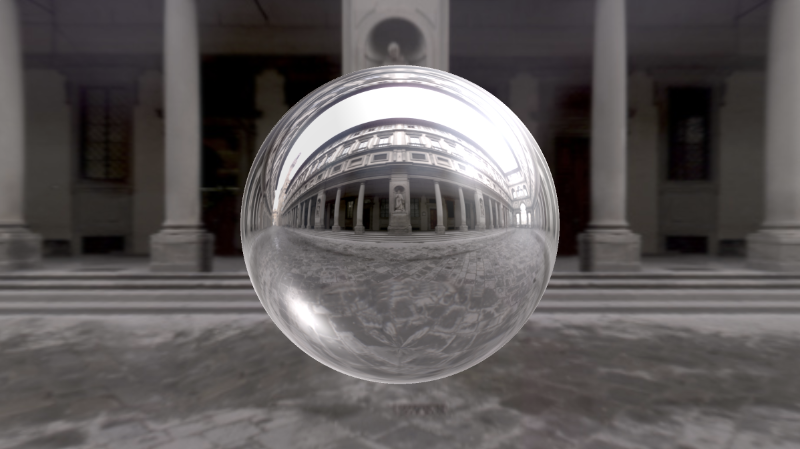
We are using the Phong reflection model we learned in Part 11 and Fresnel reflection we learned in Part 12.
Inside the phong function, we are implementing the Phong reflection model.
vec3 phong(vec3 lightDir, float lightIntensity, vec3 rd, vec3 normal) {
  vec3 cubemapReflectionColor = texture(iChannel0, reflect(rd, normal)).rgb;

  vec3 K_a = 1.5 * vec3(0.0,0.5,0.8) * cubemapReflectionColor; // Reflection
  vec3 K_d = vec3(1);
  vec3 K_s = vec3(1);
  float alpha = 50.;

  float diffuse = clamp(dot(lightDir, normal), 0., 1.);
  float specular = pow(clamp(dot(reflect(lightDir, normal), -rd), 0., 1.), alpha);

  return lightIntensity * (K_a + K_d * diffuse + K_s * specular);
}
The ambient color of the sphere will be the color of the cubemap. However, notice that instead of passing in the ray direction, rd, into the texture function, we are using the reflect function to find the reflected ray direction as if the ray bounced off the sphere. This creates the illusion of a spherical reflection, making the sphere look like a mirror.
vec3 cubemapReflectionColor = texture(iChannel0, reflect(rd, normal)).rgb;
vec3 K_a = cubemapReflectionColor;
We can also have some fun and add a blue tint to the color of the sphere.
vec3 cubemapReflectionColor = texture(iChannel0, reflect(rd, normal)).rgb;
vec3 K_a = 1.5 * vec3(0.0,0.5,0.8) * cubemapReflectionColor;
Beautiful!
How to Use the Cube A Shader
We can create custom cubemaps in Shadertoy by using the "Cube A" option. First, let's create a new shader. In the previous tutorial, we learned that we can add buffers by clicking the plus sign next to the "Image" tab at the top of the Shadertoy user interface.
Upon clicking the plus sign, we should see a menu appear. Select the "Cubemap A" option.
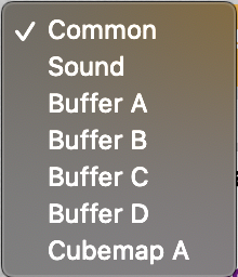
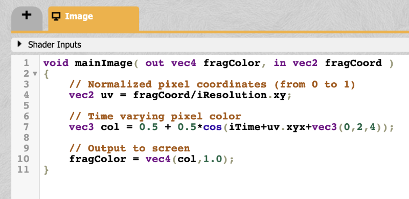
When you select the "Cubemap A" option, you should see a new tab appear to the left of the "Image" tab. This tab will say "Cube A." By default, Shadertoy will provide the following code for this "Cube A" shader.
void mainCubemap( out vec4 fragColor, in vec2 fragCoord, in vec3 rayOri, in vec3 rayDir )
{
    // Ray direction as color
    vec3 col = 0.5 + 0.5*rayDir;

    // Output to cubemap
    fragColor = vec4(col,1.0);
}
Instead of defining a mainImage function, we are now defining a mainCubemap function. It automatically provides a ray direction, rayDir, for you. It also provides a ray origin, rayOri in case you need it for performing calculations based on it.
Suppose we want to generate a custom cubemap that is red on opposite faces, blue on opposite faces, and green on opposite faces. Essentially, we're going to build a dynamic background in the shape of a cube and move the camera around using our mouse. It will look like the following.
We will replace the code in the "Cube A" shader with the following code:
float max3(vec3 rd) {
   return max(max(rd.x, rd.y), rd.z);
}

void mainCubemap( out vec4 fragColor, in vec2 fragCoord, in vec3 rayOri, in vec3 rayDir )
{
    vec3 rd = abs(rayDir);

    vec3 col = vec3(0);
    if (max3(rd) == rd.x) col = vec3(1, 0, 0);
    if (max3(rd) == rd.y) col = vec3(0, 1, 0);
    if (max3(rd) == rd.z) col = vec3(0, 0, 1);

    fragColor = vec4(col,1.0); // Output cubemap
}
Let me explain what's happening here. The max3 function is a function I created for getting the maximum value of each component of a three-dimensional vector, vec3. Inside the mainCubemap function, we're taking the absolute value of the ray direction, rayDir. Why? If we had a ray direction of vec3(1, 0, 0) and a ray direction of vec3(-1, 0, 0), then we want the pixel color to be red. Thus, opposite faces of the cube will be red.
We're taking the maximum value of each component of the ray direction to determine which component across the X, Y, and Z axis is larger. This will let us create a "square" shape.
Imagine you're looking at a cube and calculating the surface normal on each face of the cube. You would end up with six unique surface normals: vec3(1, 0, 0), vec3(0, 1, 0), vec3(0, 0, 1), vec3(-1, 0, 0), vec3(0, -1, 0), vec3(0, 0, -1). By taking the max of the ray direction, we essentially create one of these six surface normals. Since we're taking the absolute value of the ray direction, we only have to check three different scenarios.
Now that we learned how this code works, let's go back to the "Image" shader. Click on the iChannel0 box, click the "Misc" tab in the popup menu that appears, and select the "Cubemap A" option.
Then, add the following code to the "Image" shader:
const float PI = 3.14159265359;

mat2 rotate2d(float theta) {
  float s = sin(theta), c = cos(theta);
  return mat2(c, -s, s, c);
}

mat3 camera(vec3 cameraPos, vec3 lookAtPoint) {
    vec3 cd = normalize(lookAtPoint - cameraPos);
    vec3 cr = normalize(cross(vec3(0, 1, 0), cd));
    vec3 cu = normalize(cross(cd, cr));

    return mat3(-cr, cu, -cd);
}

void mainImage( out vec4 fragColor, in vec2 fragCoord )
{
  vec2 uv = (fragCoord-.5*iResolution.xy)/iResolution.y;
  vec2 mouseUV = iMouse.xy/iResolution.xy;
  if (mouseUV == vec2(0.0)) mouseUV = vec2(0.5); // trick to center mouse on page load

  vec3 lp = vec3(0);
  vec3 ro = vec3(0, 0, 3);
  ro.yz *= rotate2d(mix(-PI/2., PI/2., mouseUV.y));
  ro.xz *= rotate2d(mix(-PI, PI, mouseUV.x));

  vec3 rd = camera(ro, lp) * normalize(vec3(uv, -0.5)); // Notice how we're using -0.5 as the zoom factor instead of -1

  vec3 col = texture(iChannel0, rd).rgb;

  fragColor = vec4(col, 1.0);
}
This code is similar to what we used earlier in this tutorial. Instead of using the "Uffizi Gallery" cubemap, we are using the custom cubemap we created in the "Cube A" tab. We also zoomed out a little bit by changing the zoom factor from -1 to -0.5.
vec3 rd = camera(ro, lp) * normalize(vec3(uv, -0.5));
When you run the shader, you should see a colorful background that makes it seem like we're inside a cube. Neat!
Conclusion
In this tutorial, we learned how to use cubemaps Shadertoy provides and learned how to create our own cubemaps. We can use the texture function to access values stored in a cubemap by using the ray direction. If we want to create reflections, we can use the reflect function together with the ray direction and surface normal to create more realistic reflections. By using the "Cube A" shader, we can create custom cubemaps.