Shadertoy Tutorial Part 2 - Circles and Animation
Greetings, friends! Today, we'll talk about how to draw and animate a circle in a pixel shader using Shadertoy.
Practice
Before we draw our first 2D shape, let's practice a bit more with Shadertoy. Create a new shader and replace the starting code with the following:
void mainImage( out vec4 fragColor, in vec2 fragCoord )
{
  vec2 uv = fragCoord/iResolution.xy; // <0,1>

  vec3 col = vec3(0); // start with black

  if (uv.x > .5) col = vec3(1); // make the right half of the canvas white

  // Output to screen
  fragColor = vec4(col,1.0);
}
Since our shader is run in parallel across all pixels, we have to rely on if statements to draw pixels different colors depending on their location on the screen. Depending on your graphics card and the compiler being used for your shader code, it might be more performant to use built-in functions such as step.
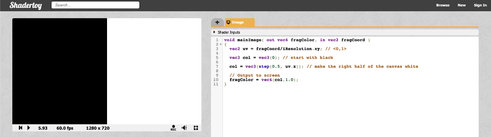
Let's look at the same example but use the step function instead:
void mainImage( out vec4 fragColor, in vec2 fragCoord )
{
  vec2 uv = fragCoord/iResolution.xy; // <0,1>

  vec3 col = vec3(0); // start with black

  col = vec3(step(0.5, uv.x)); // make the right half of the canvas white

  // Output to screen
  fragColor = vec4(col,1.0);
}
The left half of the canvas will be black and the right half of the canvas will be white.
The step function accepts two inputs: the edge of the step function, and a value used to generate the step function. If the second parameter in the function argument is greater than the first, then return a value of one. Otherwise, return a value of zero.
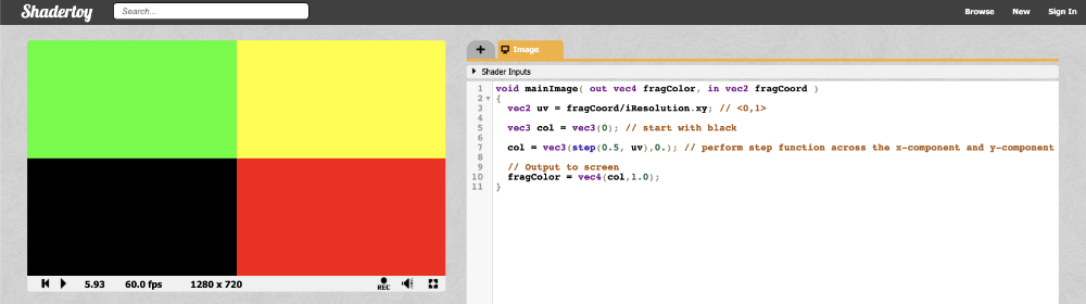
You can perform the step function across each component in a vector as well:
void mainImage( out vec4 fragColor, in vec2 fragCoord )
{
  vec2 uv = fragCoord/iResolution.xy; // <0,1>

  vec3 col = vec3(0); // start with black

  col = vec3(step(0.5, uv), 0); // perform step function across the x-component and y-component of uv

  // Output to screen
  fragColor = vec4(col,1.0);
}
Since the step function operates on both the X component and Y component of the canvas, you should see the canvas get split into four colors.
How to Draw Circles
The equation of a circle is defined by the following:
x^2 + y^2 = r^2

x = x-coordinate on graph
y = y-coordinate on graph
r = radius of circle
We can re-arrange the variables to make the equation equal to zero:
x^2 + y^2 - r^2 = 0
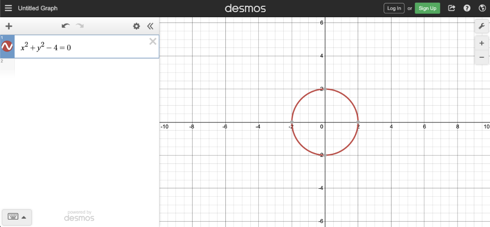
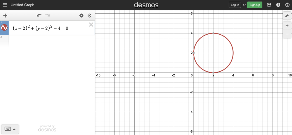
To visualize this on a graph, you can use the Desmos calculator to graph the following:
x^2 + y^2 - 4 = 0
If you copy the above snippet and paste it into the Desmos calculator, then you should see a graph of a circle with a radius of two. The center of the circle is located at the coordinate, (0, 0).
In Shadertoy, we can use the left-hand side (LHS) of this equation to make a circle. Let's create a function called sdfCircle that returns the color, white, for each pixel at an XY-coordinate such that the equation is greater than zero and the color, blue, otherwise.
The sdf part of the function refers to a concept called signed distance functions (SDF), aka signed distance fields. It's more common to use SDFs when drawing in 3D, but I will use this term for 2D shapes as well.
We will call our new function in the mainImage function to use it.
vec3 sdfCircle(vec2 uv, float r) {
    float x = uv.x;
    float y = uv.y;

    float d = length(vec2(x, y)) - r;

    return d > 0. ? vec3(1.) : vec3(0., 0., 1.);
}

void mainImage( out vec4 fragColor, in vec2 fragCoord )
{
  vec2 uv = fragCoord/iResolution.xy; // <0,1>

  vec3 col = sdfCircle(uv, .2); // Call this function on each pixel to check if the coordinate lies inside or outside of the circle

  // Output to screen
  fragColor = vec4(col,1.0);
}
If you're wondering why I use 0. instead of simply 0 without a decimal, it's because adding a decimal at the end of an integer will make it make it have a type of float instead of int. When you're using functions that require numbers that are of type float, placing a decimal at the end of an integer is the easiest way to satisfy the compiler.
We're using a radius of 0.2 because our coordinate system is set up to only have UV values that are between zero and one. When you run the code, you'll notice that something appears wrong.
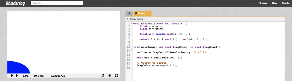
There seems to be a quarter of a blue dot in the bottom-left corner of the canvas. Why? Because our coordinate system is currently setup such that the origin is at the bottom-left corner. We need to shift every value by 0.5 to get the origin of the coordinate system at the center of the canvas.
Subtract 0.5 from the UV coordinates:
vec2 uv = fragCoord/iResolution.xy; // <0,1>
uv -= 0.5; // <-0.5, 0.5>
Now the range is between -0.5 and 0.5 on both the x-axis and y-axis, which means the origin of the coordinate system is in the center of the canvas. However, we face another issue...
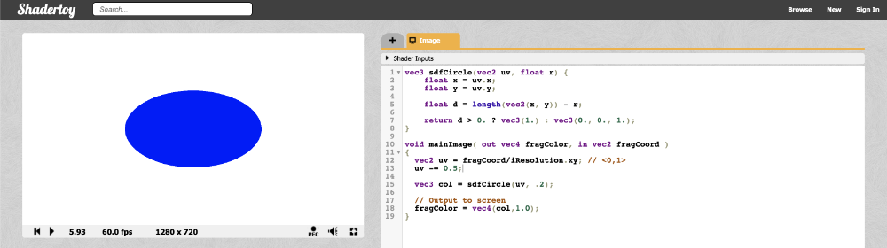
Our circle appears a bit stretched, so it looks more like an ellipse. This is caused by the aspect ratio of the canvas. When the width and the height of the canvas don't match, the circle appears stretched. We can fix this issue by multiplying the X component of the UV coordinates by the aspect ratio of the canvas.
vec2 uv = fragCoord/iResolution.xy; // <0,1>
uv -= 0.5; // <-0.5, 0.5>
uv.x *= iResolution.x/iResolution.y; // fix aspect ratio
This means the X component no longer goes between -0.5 and 0.5. It will go between values proportional to the aspect ratio of your canvas which will be determined by the width of your browser or webpage (if you're using something like Chrome DevTools to alter the width).
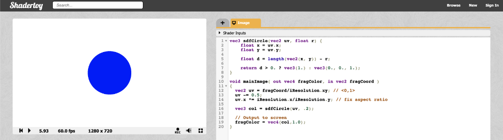
Your finished code should look like the following:
vec3 sdfCircle(vec2 uv, float r) {
  float x = uv.x;
  float y = uv.y;

  float d = length(vec2(x, y)) - r;

  return d > 0. ? vec3(1.) : vec3(0., 0., 1.);
}

void mainImage( out vec4 fragColor, in vec2 fragCoord )
{
  vec2 uv = fragCoord/iResolution.xy; // <0,1>
  uv -= 0.5;
  uv.x *= iResolution.x/iResolution.y; // fix aspect ratio

  vec3 col = sdfCircle(uv, .2);

  // Output to screen
  fragColor = vec4(col,1.0);
}
Once you run the code, you should see a perfectly proportional blue circle! 🎉
We can have some fun with this! We can use the global iTime variable to change colors over time. By using a cosine (cos) function, we can cycle through the same set of colors over and over. Since cosine functions oscillate between the values -1 and 1, we need to adjust this range to values between zero and one.
Remember, any color values in the final fragment color that are less than zero will automatically be clamped to zero. Likewise, any color values greater than one will be clamped to one. By adjusting the range, we get a wider range of colors.
vec3 sdfCircle(vec2 uv, float r) {
  float x = uv.x;
  float y = uv.y;

  float d = length(vec2(x, y)) - r;

  return d > 0. ? vec3(0.) : 0.5 + 0.5 * cos(iTime + uv.xyx + vec3(0,2,4));
}

void mainImage( out vec4 fragColor, in vec2 fragCoord )
{
  vec2 uv = fragCoord/iResolution.xy; // <0,1>
  uv -= 0.5;
  uv.x *= iResolution.x/iResolution.y; // fix aspect ratio

  vec3 col = sdfCircle(uv, .2);

  // Output to screen
  fragColor = vec4(col,1.0);
}
Once you run the code, you should see the circle change between various colors.
You might be confused by the syntax in uv.xyx. This is called Swizzling. We can create new vectors using components of a variable. Let's look at an example.
vec3 col = vec3(0.2, 0.4, 0.6);
vec3 col2 = col.xyx;
vec3 col3 = vec3(0.2, 0.4, 0.2);
In the code snippet above, col2 and col3 are identical.
Moving the Circle
To move the circle, we need to apply an offset to the XY coordinates inside the equation for a circle. Therefore, our equation will look like the following:
(x - offsetX)^2 + (y - offsetY)^2 - r^2 = 0

x = x-coordinate on graph
y = y-coordinate on graph
r = radius of circle
offsetX = how much to move the center of the circle in the x-axis
offsetY = how much to move the center of the circle in the y-axis
You can experiment in the Desmos calculator again by copying and pasting the following code:
(x - 2)^2 + (y - 2)^2 - 4 = 0
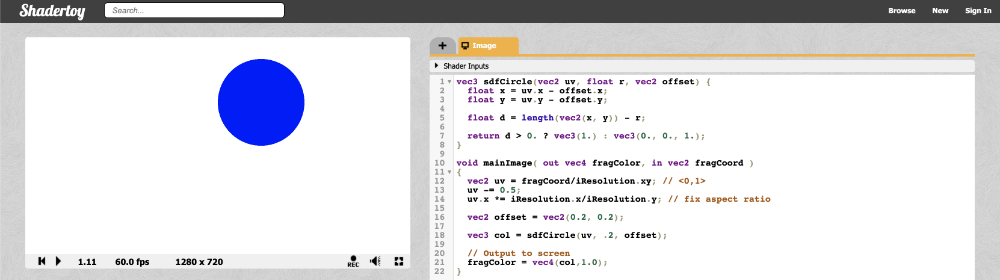
Inside Shadertoy, we can adjust our sdfCircle function to allow offsets and then move the center of the circle by 0.2.
vec3 sdfCircle(vec2 uv, float r, vec2 offset) {
  float x = uv.x - offset.x;
  float y = uv.y - offset.y;

  float d = length(vec2(x, y)) - r;

  return d > 0. ? vec3(1.) : vec3(0., 0., 1.);
}

void mainImage( out vec4 fragColor, in vec2 fragCoord )
{
  vec2 uv = fragCoord/iResolution.xy; // <0,1>
  uv -= 0.5;
  uv.x *= iResolution.x/iResolution.y; // fix aspect ratio

  vec2 offset = vec2(0.2, 0.2); // move the circle 0.2 units to the right and 0.2 units up

  vec3 col = sdfCircle(uv, .2, offset);

  // Output to screen
  fragColor = vec4(col,1.0);
}
You can again use the global iTime variable in certain places to give life to your canvas and animate your circle.
vec3 sdfCircle(vec2 uv, float r, vec2 offset) {
  float x = uv.x - offset.x;
  float y = uv.y - offset.y;

  float d = length(vec2(x, y)) - r;

  return d > 0. ? vec3(1.) : vec3(0., 0., 1.);
}

void mainImage( out vec4 fragColor, in vec2 fragCoord )
{
  vec2 uv = fragCoord/iResolution.xy; // <0,1>
  uv -= 0.5;
  uv.x *= iResolution.x/iResolution.y; // fix aspect ratio

  vec2 offset = vec2(sin(iTime*2.)*0.2, cos(iTime*2.)*0.2); // move the circle clockwise

  vec3 col = sdfCircle(uv, .2, offset);

  // Output to screen
  fragColor = vec4(col,1.0);
}
The above code will move the circle along a circular path in the clockwise direction as if it's rotating about the origin. By multiplying iTime by a value, you can speed up the animation. By multiplying the output of the sine or cosine function by a value, you can control how far the circle moves from the center of the canvas. You'll use sine and cosine functions a lot with iTime because they create oscillation.
/>
Conclusion
In this lesson, we learned how to fix the coordinate system of the canvas, draw a circle, and animate the circle along a circular path. Circles, circles, circles! 🔵
In the next lesson, I'll show you how to draw a square to the screen. Then, we'll learn how to rotate it!