Shadertoy Tutorial Part 10 - Camera Model with a Lookat Point
Greetings, friends! Welcome to Part 10 of my Shadertoy tutorial series. In this tutorial, we'll learn how to make a more flexible camera model that uses a lookat point. This will make it easier to change what objects the camera is looking at.
Initial Setup
Let's create a new shader and add the following boilerplate code we'll use for this tutorial. Notice how the constants are now defined at the top of the code.
// Constants
const int MAX_MARCHING_STEPS = 255;
const float MIN_DIST = 0.0;
const float MAX_DIST = 100.0;
const float PRECISION = 0.001;
const float EPSILON = 0.0005;
const float PI = 3.14159265359;

// Rotation matrix around the X axis.
mat3 rotateX(float theta) {
    float c = cos(theta);
    float s = sin(theta);
    return mat3(
        vec3(1, 0, 0),
        vec3(0, c, -s),
        vec3(0, s, c)
    );
}

// Rotation matrix around the Y axis.
mat3 rotateY(float theta) {
    float c = cos(theta);
    float s = sin(theta);
    return mat3(
        vec3(c, 0, s),
        vec3(0, 1, 0),
        vec3(-s, 0, c)
    );
}

// Rotation matrix around the Z axis.
mat3 rotateZ(float theta) {
    float c = cos(theta);
    float s = sin(theta);
    return mat3(
        vec3(c, -s, 0),
        vec3(s, c, 0),
        vec3(0, 0, 1)
    );
}

// Identity matrix.
mat3 identity() {
    return mat3(
        vec3(1, 0, 0),
        vec3(0, 1, 0),
        vec3(0, 0, 1)
    );
}

struct Surface {
    float sd; // signed distance value
    vec3 col; // color
};

Surface sdBox( vec3 p, vec3 b, vec3 offset, vec3 col, mat3 transform)
{
  p = (p - offset) * transform; // apply transformation matrix
  vec3 q = abs(p) - b;
  float d = length(max(q,0.0)) + min(max(q.x,max(q.y,q.z)),0.0);
  return Surface(d, col);
}

Surface sdFloor(vec3 p, vec3 col) {
  float d = p.y + 1.;
  return Surface(d, col);
}

Surface minWithColor(Surface obj1, Surface obj2) {
  if (obj2.sd < obj1.sd) return obj2;
  return obj1;
}

Surface sdScene(vec3 p) {
  vec3 floorColor = vec3(1. + 0.7*mod(floor(p.x) + floor(p.z), 2.0));
  Surface co = sdFloor(p, floorColor);
  co = minWithColor(co, sdBox(p, vec3(1), vec3(-4, 0.5, -4), vec3(1, 0, 0), identity())); // left cube
  co = minWithColor(co, sdBox(p, vec3(1), vec3(0, 0.5, -4), vec3(0, 0.65, 0.2), identity())); // center cube
  co = minWithColor(co, sdBox(p, vec3(1), vec3(4, 0.5, -4), vec3(0, 0.55, 2), identity())); // right cube
  return co;
}

Surface rayMarch(vec3 ro, vec3 rd, float start, float end) {
  float depth = start;
  Surface co; // closest object

  for (int i = 0; i < MAX_MARCHING_STEPS; i++) {
    vec3 p = ro + depth * rd;
    co = sdScene(p);
    depth += co.sd;
    if (co.sd < PRECISION || depth > end) break;
  }

  co.sd = depth;

  return co;
}

vec3 calcNormal(in vec3 p) {
    vec2 e = vec2(1, -1) * EPSILON;
    return normalize(
      e.xyy * sdScene(p + e.xyy).sd +
      e.yyx * sdScene(p + e.yyx).sd +
      e.yxy * sdScene(p + e.yxy).sd +
      e.xxx * sdScene(p + e.xxx).sd);
}

void mainImage( out vec4 fragColor, in vec2 fragCoord )
{
  vec2 uv = (fragCoord-.5*iResolution.xy)/iResolution.y;
  vec3 backgroundColor = vec3(0.835, 1, 1);

  vec3 col = vec3(0);
  vec3 ro = vec3(0, 0, 3); // ray origin that represents camera position
  vec3 rd = normalize(vec3(uv, -1)); // ray direction

  Surface co = rayMarch(ro, rd, MIN_DIST, MAX_DIST); // closest object

  if (co.sd > MAX_DIST) {
    col = backgroundColor; // ray didn't hit anything
  } else {
    vec3 p = ro + rd * co.sd; // point on cube or floor we discovered from ray marching
    vec3 normal = calcNormal(p);
    vec3 lightPosition = vec3(2, 2, 7);
    vec3 lightDirection = normalize(lightPosition - p);

    float dif = clamp(dot(normal, lightDirection), 0.3, 1.); // diffuse reflection

    col = dif * co.col + backgroundColor * .2; // Add a bit of background color to the diffuse color
  }

  // Output to screen
  fragColor = vec4(col, 1.0);
}
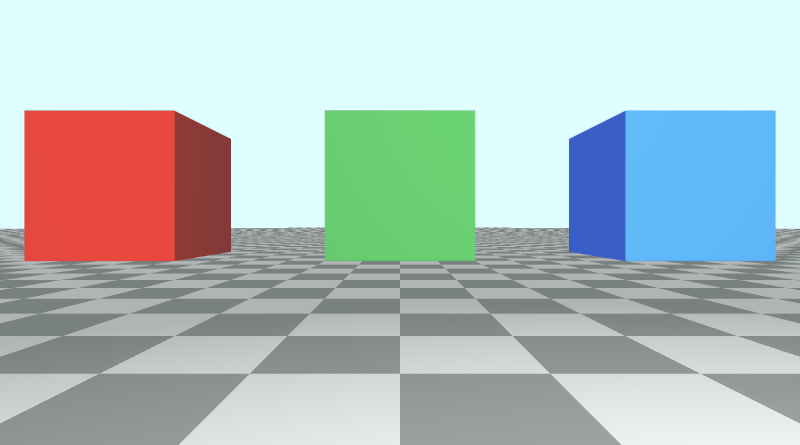
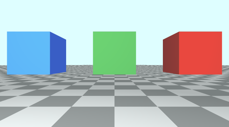
This code will produce a scene with three cubes, each with different colors: red, green, and blue.
The LookAt Point
Currently, when we want to move the camera, we have to adjust the values of the ray origin. To tilt the camera, we need to multiply the ray direction by a rotation matrix.
An alternative approach is to create a camera function that accepts the camera position (or ray origin), and a lookat point. Then, this function will return a 3x3 transformation matrix we can multiply the ray direction by.
mat3 camera(vec3 cameraPos, vec3 lookAtPoint) {
    vec3 cd = normalize(lookAtPoint - cameraPos); // camera direction
    vec3 cr = normalize(cross(vec3(0, 1, 0), cd)); // camera right
    vec3 cu = normalize(cross(cd, cr)); // camera up

    return mat3(-cr, cu, -cd);
}
To understand how we came up with this matrix, let's look at the image below. It was created on the website, Learn OpenGL, an amazing resource for learning the OpenGL graphics API.
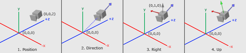
The image above conveys a lot about how the 3x3 matrix was created. We need to figure out where the camera is looking at and how it's tilted by analyzing three important camera vectors: the "camera direction" vector, the "camera right" vector, and the "camera up" vector.
In step 1, we start with the camera position, which is equal to the ray origin, ro, in our code.
In step 2, we create a camera direction vector that is relative to a "lookat" point. In the image, the lookat point is located at the origin in 3D space, but we can shift this point anywhere we want. Notice how the camera direction is pointing away from the camera. This means it's using the right-hand rule we learned about in Part 6.
vec3 cd = normalize(lookAtPoint - cameraPos); // camera direction
In step 3, there is a gray vector pointing straight up from the camera. The direction vector, (0, 1, 0), represents a unit vector for the y-axis. we create the "camera right" vector by taking the cross product between the unit vector of the y-axis and the camera direction. This creates the red vector pointing to the right of the camera.
normalize(cross(vec3(0, 1, 0), cd)); // camera right
In step 4, we then find the "camera up" vector by taking the cross product between the camera direction vector and the "camera right" vector. This "camera up" vector is depicted in the image by a green vector sticking out of the camera.
vec3 cu = normalize(cross(cd, cr)); // camera up
Finally, we create a transformation matrix by combining these vectors together:
mat3 camera(vec3 cameraPos, vec3 lookAtPoint) {
    vec3 cd = normalize(lookAtPoint - cameraPos); // camera direction
    vec3 cr = normalize(cross(vec3(0, 1, 0), cd)); // camera right
    vec3 cu = normalize(cross(cd, cr)); // camera up

    return mat3(-cr, cu, -cd); // negative signs can be turned positive (or vice versa) to flip coordinate space conventions
}
Let's look at the return statement for the camera function:
return mat3(-cr, cu, -cd);
Where did the negative signs come from? It's up to us to define a convention for how we want to label which direction is positive or negative for each axis in 3D space. This is the convention I will use in this tutorial. We'll see what happens when we flip the signs soon.
Applying the Camera Matrix
Now that we have created a camera function, let's use it in our mainImage function. We'll create a lookat point and pass it to the camera function. Then, we'll multiply the matrix it returns by the ray direction, similar to what we did in Part 9.
vec3 lp = vec3(0, 0, 0); // lookat point (aka camera target)
vec3 ro = vec3(0, 0, 3); // ray origin that represents camera position
vec3 rd = camera(ro, lp) * normalize(vec3(uv, -1)); // ray direction
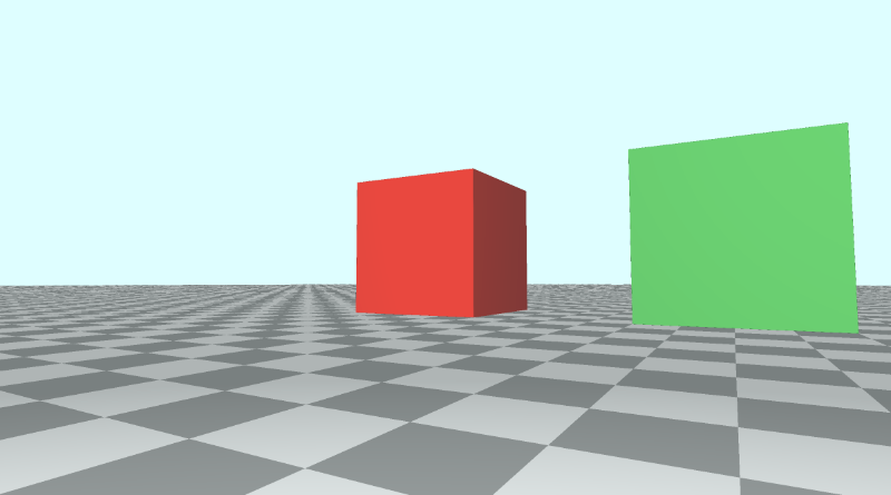
When you run your code, the scene should look almost the same. However, the camera is now targeting the origin in 3D space. Since the cubes are 0.5 units off the ground, the camera is slightly tilted from the center. We can point the camera directly at the center of the green cube by changing the lookat point to match the position of the green cube.
vec3 lp = vec3(0, 0.5, -4);
Suppose we want to look at the red cube now. It currently has the position, (-4, 0.5, -4) in 3D space. Let's change the lookat point to match that position.
vec3 lp = vec3(-4, 0.5, -4);
You should see the camera now pointing at the red cube, and it should be in the center of the canvas.
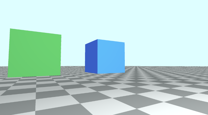
Let's now look at the blue cube. It has the position, (4, 0.5, -4) in 3D space, so we'll change the lookat point to equal that value.
vec3 lp = vec3(4, 0.5, -4);
You should see the camera now pointing at the blue cube, and it should be in the center of the canvas.
You can find the finished code below:
// Constants
const int MAX_MARCHING_STEPS = 255;
const float MIN_DIST = 0.0;
const float MAX_DIST = 100.0;
const float PRECISION = 0.001;
const float EPSILON = 0.0005;
const float PI = 3.14159265359;

// Rotation matrix around the X axis.
mat3 rotateX(float theta) {
    float c = cos(theta);
    float s = sin(theta);
    return mat3(
        vec3(1, 0, 0),
        vec3(0, c, -s),
        vec3(0, s, c)
    );
}

// Rotation matrix around the Y axis.
mat3 rotateY(float theta) {
    float c = cos(theta);
    float s = sin(theta);
    return mat3(
        vec3(c, 0, s),
        vec3(0, 1, 0),
        vec3(-s, 0, c)
    );
}

// Rotation matrix around the Z axis.
mat3 rotateZ(float theta) {
    float c = cos(theta);
    float s = sin(theta);
    return mat3(
        vec3(c, -s, 0),
        vec3(s, c, 0),
        vec3(0, 0, 1)
    );
}

// Identity matrix.
mat3 identity() {
    return mat3(
        vec3(1, 0, 0),
        vec3(0, 1, 0),
        vec3(0, 0, 1)
    );
}

struct Surface {
    float sd; // signed distance value
    vec3 col; // color
};

Surface sdBox( vec3 p, vec3 b, vec3 offset, vec3 col, mat3 transform)
{
  p = (p - offset) * transform; // apply transformation matrix
  vec3 q = abs(p) - b;
  float d = length(max(q,0.0)) + min(max(q.x,max(q.y,q.z)),0.0);
  return Surface(d, col);
}

Surface sdFloor(vec3 p, vec3 col) {
  float d = p.y + 1.;
  return Surface(d, col);
}

Surface minWithColor(Surface obj1, Surface obj2) {
  if (obj2.sd < obj1.sd) return obj2;
  return obj1;
}

Surface sdScene(vec3 p) {
  vec3 floorColor = vec3(1. + 0.7*mod(floor(p.x) + floor(p.z), 2.0));
  Surface co = sdFloor(p, floorColor);
  co = minWithColor(co, sdBox(p, vec3(1), vec3(-4, 0.5, -4), vec3(1, 0, 0), identity())); // left cube
  co = minWithColor(co, sdBox(p, vec3(1), vec3(0, 0.5, -4), vec3(0, 0.65, 0.2), identity())); // center cube
  co = minWithColor(co, sdBox(p, vec3(1), vec3(4, 0.5, -4), vec3(0, 0.55, 2), identity())); // right cube
  return co;
}

Surface rayMarch(vec3 ro, vec3 rd, float start, float end) {
  float depth = start;
  Surface co; // closest object

  for (int i = 0; i < MAX_MARCHING_STEPS; i++) {
    vec3 p = ro + depth * rd;
    co = sdScene(p);
    depth += co.sd;
    if (co.sd < PRECISION || depth > end) break;
  }

  co.sd = depth;

  return co;
}

vec3 calcNormal(in vec3 p) {
    vec2 e = vec2(1, -1) * EPSILON;
    return normalize(
      e.xyy * sdScene(p + e.xyy).sd +
      e.yyx * sdScene(p + e.yyx).sd +
      e.yxy * sdScene(p + e.yxy).sd +
      e.xxx * sdScene(p + e.xxx).sd);
}

mat3 camera(vec3 cameraPos, vec3 lookAtPoint) {
    vec3 cd = normalize(lookAtPoint - cameraPos); // camera direction
    vec3 cr = normalize(cross(vec3(0, 1, 0), cd)); // camera right
    vec3 cu = normalize(cross(cd, cr)); // camera up

    return mat3(-cr, cu, -cd);
}

void mainImage( out vec4 fragColor, in vec2 fragCoord )
{
  vec2 uv = (fragCoord-.5*iResolution.xy)/iResolution.y;
  vec3 backgroundColor = vec3(0.835, 1, 1);

  vec3 col = vec3(0);
  vec3 lp = vec3(4, 0.5, -4); // lookat point (aka camera target)
  vec3 ro = vec3(0, 0, 3); // ray origin that represents camera position
  vec3 rd = camera(ro, lp) * normalize(vec3(uv, -1)); // ray direction

  Surface co = rayMarch(ro, rd, MIN_DIST, MAX_DIST); // closest object

  if (co.sd > MAX_DIST) {
    col = backgroundColor; // ray didn't hit anything
  } else {
    vec3 p = ro + rd * co.sd; // point on cube or floor we discovered from ray marching
    vec3 normal = calcNormal(p);
    vec3 lightPosition = vec3(2, 2, 7);
    vec3 lightDirection = normalize(lightPosition - p);

    float dif = clamp(dot(normal, lightDirection), 0.3, 1.); // diffuse reflection

    col = dif * co.col + backgroundColor * .2; // Add a bit of background color to the diffuse color
  }

  // Output to screen
  fragColor = vec4(col, 1.0);
}
Adjusting the Sign Convention
Earlier, we saw that the camera function returns a matrix consisting of the three camera vectors.
mat3 camera(vec3 cameraPos, vec3 lookAtPoint) {
    vec3 cd = normalize(lookAtPoint - cameraPos); // camera direction
    vec3 cr = normalize(cross(vec3(0, 1, 0), cd)); // camera right
    vec3 cu = normalize(cross(cd, cr)); // camera up

    return mat3(-cr, cu, -cd);
}
If we setup the lookat point to point the camera at the green cube, we have the following code:
vec3 lp = vec3(0, 0.5, -4); // lookat point (aka camera target)
vec3 ro = vec3(0, 0, 3); // ray origin that represents camera position
vec3 rd = camera(ro, lp) * normalize(vec3(uv, -1)); // ray direction
This produces the scene from the beginning of this tutorial where the red cube is on the left of the green cube, and the blue cube is on the right of the green cube.
If we decide to use a positive cr value in the camera function, then let's see what happens.
The red cube and blue cube seem to switch places, but pay attention to the floor tiles. They are switched too. The "camera right" vector is reversed which causes the whole scene to flip like looking at a mirror image of the original scene.
Using a positive cr impacts what the camera sees and also makes the position of our cubes seem confusing. Our x-axis is designed to be negative on the left of the center of the canvas and positive on the right of the center. Flipping cr means flipping that convention too.
If we flipped the value of the camera direction, cd to be positive instead of negative, it would turn the camera around because it would flip our z-axis convention.
Another way you can flip the z-axis convention is by using a positive value for the z-component of the ray direction.
vec3 rd = normalize(vec3(uv, 1)); // positive one is being used instead of negative one
When you use this alternative camera model with a lookat point, it's good to know the conventions you've set for what's positive or negative across each axis.
You can play around with cr, cu, and cd to make some interesting effects. Make sure to change the ray direction, rd, back to using negative one.
The following code can create a slingshot effect across the z-axis to make it look like the camera zooms out and zooms in really quickly. Maybe this could be used to create a "warp drive" effect? 🤔
mat3 camera(vec3 cameraPos, vec3 lookAtPoint) {
    vec3 cd = normalize(lookAtPoint - cameraPos); // camera direction
    vec3 cr = normalize(cross(vec3(0, 1, 0), cd)); // camera right
    vec3 cu = normalize(cross(cd, cr)); // camera up

    return mat3(-cr, cu, abs(cos(iTime)) * -cd);
}
Go ahead and change the camera matrix back to normal before continuing to the next part of the tutorial.
mat3 camera(vec3 cameraPos, vec3 lookAtPoint) {
    vec3 cd = normalize(lookAtPoint - cameraPos); // camera direction
    vec3 cr = normalize(cross(vec3(0, 1, 0), cd)); // camera right
    vec3 cu = normalize(cross(cd, cr)); // camera up

    return mat3(-cr, cu, -cd);
}
Rotating the Camera Around a Target
Suppose we wanted to rotate our camera in a circular path around the scene while keeping our camera pointed at the green cube. We'll keep the camera at a constant height (y-component) above the floor. Since all three cubes have a position with a y-component of 0.5, we will make sure the y-component of ro, the ray origin (camera position), equals 0.5 as well.
If we want to make the camera follow a circular path around the size of the cubes, then we should focus on changing the x-component and z-component of the ray origin, ro.
If we looked at the cubes from a top-down perspective, then we would see a view similar to the following illustration.
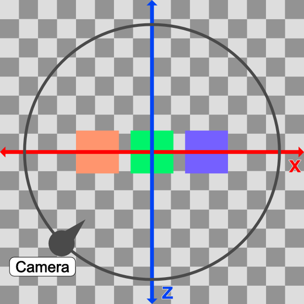
In the image above, the camera will follow a circular path (black). From a top-down perspective, the scene appears 2D with just an x-axis (red) and z-axis (blue).
The idea is to alter the x-component and z-component values of ro such that it follows a circular path. We can accomplish this by converting ro.x and ro.z into polar coordinates.
vec3 ro = vec3(0, 0.5, 0);
ro.x = cameraRadius * cos(theta);
ro.z = cameraRadius * sin(theta);
The value of the camera radius will be increased until we can see all the cubes in our scene. We currently have three cubes at the following positions in 3D space (defined in the sdScene function):
vec3(-4, 0.5, -4) // left cube
vec3(0, 0.5, -4) // center cube
vec3(4, 0.5, -4) // right cube
Therefore, it might be safe to make the radius something like 10 because the distance between the left cube and right cube is 4 - (-4) = 8 units.
In our code, we'll convert the x-component and z-component of the ray origin to polar coordinates with a radius of ten. Then, we'll also shift our circular path by an offset such that the lookat point is the center of the circle made by the circular path.
vec3 lp = vec3(0, 0.5, -4); // lookat point (aka camera target)
vec3 ro = vec3(0, 0.5, 0); // ray origin that represents camera position

float cameraRadius = 10.;
ro.x = cameraRadius * cos(iTime) + lp.x; // convert x-component to polar and add offset
ro.z = cameraRadius * sin(iTime) + lp.z; // convert z-component to polar and add offset

vec3 rd = camera(ro, lp) * normalize(vec3(uv, -1)); // ray direction
When you run the code, you should see the camera spinning around the scene because it's following a circular path, but it's still looking at the green cube using our lookat point.
From a top-down perspective, our camera is moving in a circle that is offset by the lookat point's x-component and z-component, so we can make sure the lookat point stays in the center of our circle. This ensures that the distance from the green cube, the radius of the circle, stays equidistant from the green cube throughout the whole revolution.
You can use the graph I created on Desmos to experiment with the circular path. Imagine the green cube is located in the center of the circle.
Using a lookat point makes our camera more flexible. We can raise the camera higher along the y-axis and rotate around in a circle again, but get a bird's-eye view of the cubes instead.
Let's try adjusting the height of the camera (ray origin) and see what happens.
vec3 ro = vec3(0, 5, 0);
When we run the code, we should see the camera now circling around the three cubes, but it's at a higher position. It's like we're a news reporter flying around in a helicopter.
If you change the lookat point, you should start rotating around that new point instead!
You can find the finished code below:
// Constants
const int MAX_MARCHING_STEPS = 255;
const float MIN_DIST = 0.0;
const float MAX_DIST = 100.0;
const float PRECISION = 0.001;
const float EPSILON = 0.0005;
const float PI = 3.14159265359;

// Rotation matrix around the X axis.
mat3 rotateX(float theta) {
    float c = cos(theta);
    float s = sin(theta);
    return mat3(
        vec3(1, 0, 0),
        vec3(0, c, -s),
        vec3(0, s, c)
    );
}

// Rotation matrix around the Y axis.
mat3 rotateY(float theta) {
    float c = cos(theta);
    float s = sin(theta);
    return mat3(
        vec3(c, 0, s),
        vec3(0, 1, 0),
        vec3(-s, 0, c)
    );
}

// Rotation matrix around the Z axis.
mat3 rotateZ(float theta) {
    float c = cos(theta);
    float s = sin(theta);
    return mat3(
        vec3(c, -s, 0),
        vec3(s, c, 0),
        vec3(0, 0, 1)
    );
}

// Identity matrix.
mat3 identity() {
    return mat3(
        vec3(1, 0, 0),
        vec3(0, 1, 0),
        vec3(0, 0, 1)
    );
}

struct Surface {
    float sd; // signed distance value
    vec3 col; // color
};

Surface sdBox( vec3 p, vec3 b, vec3 offset, vec3 col, mat3 transform)
{
  p = (p - offset) * transform; // apply transformation matrix
  vec3 q = abs(p) - b;
  float d = length(max(q,0.0)) + min(max(q.x,max(q.y,q.z)),0.0);
  return Surface(d, col);
}

Surface sdFloor(vec3 p, vec3 col) {
  float d = p.y + 1.;
  return Surface(d, col);
}

Surface minWithColor(Surface obj1, Surface obj2) {
  if (obj2.sd < obj1.sd) return obj2;
  return obj1;
}

Surface sdScene(vec3 p) {
  vec3 floorColor = vec3(1. + 0.7*mod(floor(p.x) + floor(p.z), 2.0));
  Surface co = sdFloor(p, floorColor);
  co = minWithColor(co, sdBox(p, vec3(1), vec3(-4, 0.5, -4), vec3(1, 0, 0), identity())); // left cube
  co = minWithColor(co, sdBox(p, vec3(1), vec3(0, 0.5, -4), vec3(0, 0.65, 0.2), identity())); // center cube
  co = minWithColor(co, sdBox(p, vec3(1), vec3(4, 0.5, -4), vec3(0, 0.55, 2), identity())); // right cube
  return co;
}

Surface rayMarch(vec3 ro, vec3 rd, float start, float end) {
  float depth = start;
  Surface co; // closest object

  for (int i = 0; i < MAX_MARCHING_STEPS; i++) {
    vec3 p = ro + depth * rd;
    co = sdScene(p);
    depth += co.sd;
    if (co.sd < PRECISION || depth > end) break;
  }

  co.sd = depth;

  return co;
}

vec3 calcNormal(in vec3 p) {
    vec2 e = vec2(1, -1) * EPSILON;
    return normalize(
      e.xyy * sdScene(p + e.xyy).sd +
      e.yyx * sdScene(p + e.yyx).sd +
      e.yxy * sdScene(p + e.yxy).sd +
      e.xxx * sdScene(p + e.xxx).sd);
}

mat3 camera(vec3 cameraPos, vec3 lookAtPoint) {
    vec3 cd = normalize(lookAtPoint - cameraPos); // camera direction
    vec3 cr = normalize(cross(vec3(0, 1, 0), cd)); // camera right
    vec3 cu = normalize(cross(cd, cr)); // camera up

    return mat3(-cr, cu, -cd);
}

void mainImage( out vec4 fragColor, in vec2 fragCoord )
{
  vec2 uv = (fragCoord-.5*iResolution.xy)/iResolution.y;
  vec3 backgroundColor = vec3(0.835, 1, 1);

  vec3 col = vec3(0);
  vec3 lp = vec3(0, 0.5, -4); // lookat point (aka camera target)
  vec3 ro = vec3(0, 5, 0); // ray origin that represents camera position

  float cameraRadius = 10.;
  ro.x = cameraRadius * cos(iTime) + lp.x; // convert to polar
  ro.z = cameraRadius * sin(iTime) + lp.z;

  vec3 rd = camera(ro, lp) * normalize(vec3(uv, -1)); // ray direction

  Surface co = rayMarch(ro, rd, MIN_DIST, MAX_DIST); // closest object

  if (co.sd > MAX_DIST) {
    col = backgroundColor; // ray didn't hit anything
  } else {
    vec3 p = ro + rd * co.sd; // point on cube or floor we discovered from ray marching
    vec3 normal = calcNormal(p);
    vec3 lightPosition = vec3(2, 2, 7);
    vec3 lightDirection = normalize(lightPosition - p);

    float dif = clamp(dot(normal, lightDirection), 0.3, 1.); // diffuse reflection

    col = dif * co.col + backgroundColor * .2; // Add a bit of background color to the diffuse color
  }

  // Output to screen
  fragColor = vec4(col, 1.0);
}
Rotating the Camera with the Mouse
You can also use the mouse to move the camera around the scene, but it requires some extra setup. As we learned in Part 9 of this tutorial series, the iMouse global variable provides the mouse position data.
We can create "mouse UV" coordinates using the following line:
vec2 mouseUV = iMouse.xy/iResolution.xy; // Range: <0, 1>
We'll replace the following three lines, since we're using our mouse to rotate around the scene instead of using time.
float cameraRadius = 10.;
ro.x = cameraRadius * cos(iTime) + lp.x; // convert to polar
ro.z = cameraRadius * sin(iTime) + lp.z;
The following code will replace the above code:
float cameraRadius = 2.;
ro.yz = ro.yz * cameraRadius * rotate2d(mix(PI/2., 0., mouseUV.y));
ro.xz = ro.xz * rotate2d(mix(-PI, PI, mouseUV.x)) + vec2(lp.x, lp.z); // remap mouseUV.x to <-pi, pi> range
Again, we're using the mix function to remap the x-component of the mouse position. This time, we're remapping values from the <0,1> range to the <-π, π> range. We also need to add the x-component and z-component of the lookat point.
Notice that we have a rotate2d function that doesn't specify an axis. This function will provide a 2D rotation using a 2D matrix. Add the following function at the top of your code.
mat2 rotate2d(float theta) {
  float s = sin(theta), c = cos(theta);
  return mat2(c, -s, s, c);
}
Like before, you may need to play around with the cameraRadius until it looks decent. Your finished code should look like the following:
// Constants
const int MAX_MARCHING_STEPS = 255;
const float MIN_DIST = 0.0;
const float MAX_DIST = 100.0;
const float PRECISION = 0.001;
const float EPSILON = 0.0005;
const float PI = 3.14159265359;

// Rotate around a circular path
mat2 rotate2d(float theta) {
  float s = sin(theta), c = cos(theta);
  return mat2(c, -s, s, c);
}

// Rotation matrix around the X axis.
mat3 rotateX(float theta) {
    float c = cos(theta);
    float s = sin(theta);
    return mat3(
        vec3(1, 0, 0),
        vec3(0, c, -s),
        vec3(0, s, c)
    );
}

// Rotation matrix around the Y axis.
mat3 rotateY(float theta) {
    float c = cos(theta);
    float s = sin(theta);
    return mat3(
        vec3(c, 0, s),
        vec3(0, 1, 0),
        vec3(-s, 0, c)
    );
}

// Rotation matrix around the Z axis.
mat3 rotateZ(float theta) {
    float c = cos(theta);
    float s = sin(theta);
    return mat3(
        vec3(c, -s, 0),
        vec3(s, c, 0),
        vec3(0, 0, 1)
    );
}

// Identity matrix.
mat3 identity() {
    return mat3(
        vec3(1, 0, 0),
        vec3(0, 1, 0),
        vec3(0, 0, 1)
    );
}

struct Surface {
    float sd; // signed distance value
    vec3 col; // color
};

Surface sdBox( vec3 p, vec3 b, vec3 offset, vec3 col, mat3 transform)
{
  p = (p - offset) * transform; // apply transformation matrix
  vec3 q = abs(p) - b;
  float d = length(max(q,0.0)) + min(max(q.x,max(q.y,q.z)),0.0);
  return Surface(d, col);
}

Surface sdFloor(vec3 p, vec3 col) {
  float d = p.y + 1.;
  return Surface(d, col);
}

Surface minWithColor(Surface obj1, Surface obj2) {
  if (obj2.sd < obj1.sd) return obj2;
  return obj1;
}

Surface sdScene(vec3 p) {
  vec3 floorColor = vec3(1. + 0.7*mod(floor(p.x) + floor(p.z), 2.0));
  Surface co = sdFloor(p, floorColor);
  co = minWithColor(co, sdBox(p, vec3(1), vec3(-4, 0.5, -4), vec3(1, 0, 0), identity())); // left cube
  co = minWithColor(co, sdBox(p, vec3(1), vec3(0, 0.5, -4), vec3(0, 0.65, 0.2), identity())); // center cube
  co = minWithColor(co, sdBox(p, vec3(1), vec3(4, 0.5, -4), vec3(0, 0.55, 2), identity())); // right cube
  return co;
}

Surface rayMarch(vec3 ro, vec3 rd, float start, float end) {
  float depth = start;
  Surface co; // closest object

  for (int i = 0; i < MAX_MARCHING_STEPS; i++) {
    vec3 p = ro + depth * rd;
    co = sdScene(p);
    depth += co.sd;
    if (co.sd < PRECISION || depth > end) break;
  }

  co.sd = depth;

  return co;
}

vec3 calcNormal(in vec3 p) {
    vec2 e = vec2(1, -1) * EPSILON;
    return normalize(
      e.xyy * sdScene(p + e.xyy).sd +
      e.yyx * sdScene(p + e.yyx).sd +
      e.yxy * sdScene(p + e.yxy).sd +
      e.xxx * sdScene(p + e.xxx).sd);
}

mat3 camera(vec3 cameraPos, vec3 lookAtPoint) {
    vec3 cd = normalize(lookAtPoint - cameraPos); // camera direction
    vec3 cr = normalize(cross(vec3(0, 1, 0), cd)); // camera right
    vec3 cu = normalize(cross(cd, cr)); // camera up

    return mat3(-cr, cu, -cd);
}

void mainImage( out vec4 fragColor, in vec2 fragCoord )
{
  vec2 uv = (fragCoord-.5*iResolution.xy)/iResolution.y;
  vec2 mouseUV = iMouse.xy/iResolution.xy; // Range: <0, 1>
  vec3 backgroundColor = vec3(0.835, 1, 1);

  vec3 col = vec3(0);
  vec3 lp = vec3(0, 0.5, -4); // lookat point (aka camera target)
  vec3 ro = vec3(0, 5, 0); // ray origin that represents camera position

  float cameraRadius = 2.;
  ro.yz = ro.yz * cameraRadius * rotate2d(mix(PI/2., 0., mouseUV.y));
  ro.xz = ro.xz * rotate2d(mix(-PI, PI, mouseUV.x)) + vec2(lp.x, lp.z);

  vec3 rd = camera(ro, lp) * normalize(vec3(uv, -1)); // ray direction

  Surface co = rayMarch(ro, rd, MIN_DIST, MAX_DIST); // closest object

  if (co.sd > MAX_DIST) {
    col = backgroundColor; // ray didn't hit anything
  } else {
    vec3 p = ro + rd * co.sd; // point on cube or floor we discovered from ray marching
    vec3 normal = calcNormal(p);
    vec3 lightPosition = vec3(2, 2, 7);
    vec3 lightDirection = normalize(lightPosition - p);

    float dif = clamp(dot(normal, lightDirection), 0.3, 1.); // diffuse reflection

    col = dif * co.col + backgroundColor * .2; // Add a bit of background color to the diffuse color
  }

  // Output to screen
  fragColor = vec4(col, 1.0);
}
Now, you use your mouse to rotate around the scene! 🎉 More specifically, you can use your mouse to rotate around your lookat point.
Conclusion
I hope you now see how powerful this alternative camera model can be! The lookat point can make it easier to move the camera around the scene while focusing on a single target.