Shadertoy Tutorial Part 5 - 2D SDF Operations and More 2D Shapes
Greetings, friends! In this tutorial, I'll discuss how to use 2D SDF operations to create more complex shapes from primitive shapes, and I'll discuss how to draw more primitive 2D shapes, including hearts and stars. I'll help you utilize this list of 2D SDFs that was popularized by the talented Inigo Quilez, one of the co-creators of Shadertoy. Let's begin!
Combination 2D SDF Operations
In the previous tutorials, we've seen how to draw primitive 2D shapes such as circles and squares, but we can use 2D SDF operations to create more complex shapes by combining primitive shapes together.
Let's start with some simple boilerplate code for 2D shapes:
vec3 getBackgroundColor(vec2 uv) {
  uv = uv * 0.5 + 0.5; // remap uv from <-0.5,0.5> to <0.25,0.75>
  vec3 gradientStartColor = vec3(1., 0., 1.);
  vec3 gradientEndColor = vec3(0., 1., 1.);
  return mix(gradientStartColor, gradientEndColor, uv.y); // gradient goes from bottom to top
}

float sdCircle(vec2 uv, float r, vec2 offset) {
  float x = uv.x - offset.x;
  float y = uv.y - offset.y;

  return length(vec2(x, y)) - r;
}

float sdSquare(vec2 uv, float size, vec2 offset) {
  float x = uv.x - offset.x;
  float y = uv.y - offset.y;

  return max(abs(x), abs(y)) - size;
}

vec3 drawScene(vec2 uv) {
  vec3 col = getBackgroundColor(uv);
  float d1 = sdCircle(uv, 0.1, vec2(0., 0.));
  float d2 = sdSquare(uv, 0.1, vec2(0.1, 0));

  float res; // result
  res = d1;

  res = step(0., res); // Same as res > 0. ? 1. : 0.;

  col = mix(vec3(1,0,0), col, res);
  return col;
}

void mainImage( out vec4 fragColor, in vec2 fragCoord )
{
  vec2 uv = fragCoord/iResolution.xy; // <0, 1>
  uv -= 0.5; // <-0.5,0.5>
  uv.x *= iResolution.x/iResolution.y; // fix aspect ratio

  vec3 col = drawScene(uv);

  fragColor = vec4(col,1.0); // Output to screen
}
Please note how I'm now using sdCircle for the function name instead of sdfCircle (which was used in previous tutorials). Inigo Quilez's website commonly uses sd in front of the shape name, but I was using sdf to help make it clear that these are signed distance fields (SDF).
When you run the code, you should see a red circle with a gradient background color, similar to what we learned in the previous tutorial.
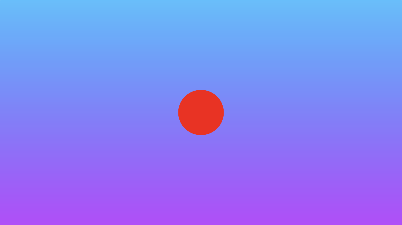
Pay attention to where we use the mix function:
col = mix(vec3(1,0,0), col, res);
This line says to take the result and either pick the color red or the value of col (currently the background color) depending on the value of res (the result).
Now, let's discuss the various SDF operations that can be performed. We will look at the interaction between a circle and a square.
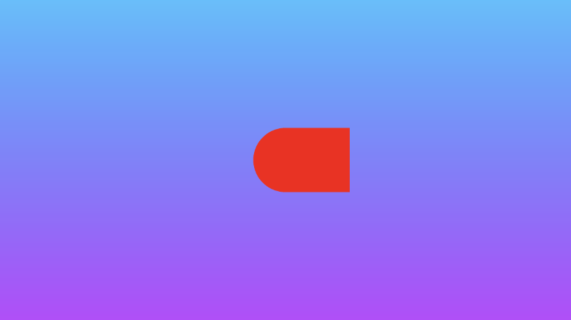
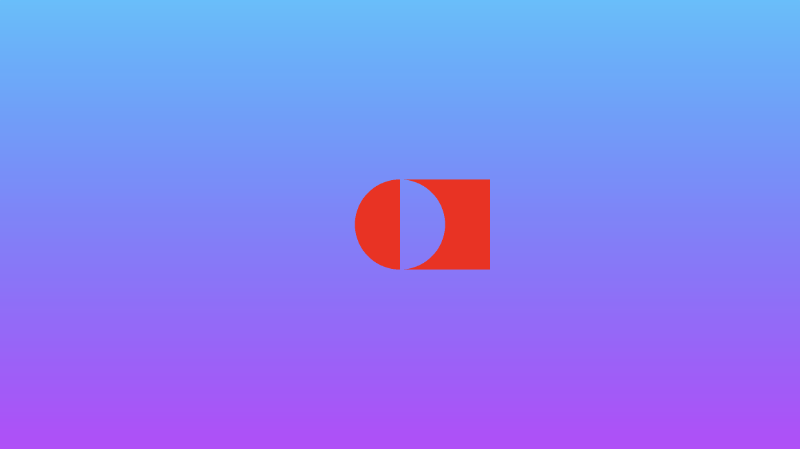
Union: combine two shapes together.
vec3 drawScene(vec2 uv) {
  vec3 col = getBackgroundColor(uv);
  float d1 = sdCircle(uv, 0.1, vec2(0., 0.));
  float d2 = sdSquare(uv, 0.1, vec2(0.1, 0));

  float res; // result
  res = min(d1, d2); // union

  res = step(0., res); // Same as res > 0. ? 1. : 0.;

  col = mix(vec3(1,0,0), col, res);
  return col;
}
Intersection: take only the part where the two shapes intersect.
vec3 drawScene(vec2 uv) {
  vec3 col = getBackgroundColor(uv);
  float d1 = sdCircle(uv, 0.1, vec2(0., 0.));
  float d2 = sdSquare(uv, 0.1, vec2(0.1, 0));

  float res; // result
  res = max(d1, d2); // intersection

  res = step(0., res); // Same as res > 0. ? 1. : 0.;

  col = mix(vec3(1,0,0), col, res);
  return col;
}
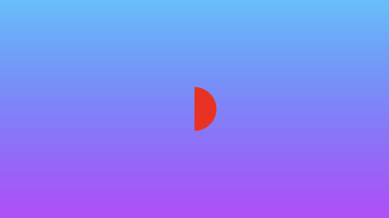
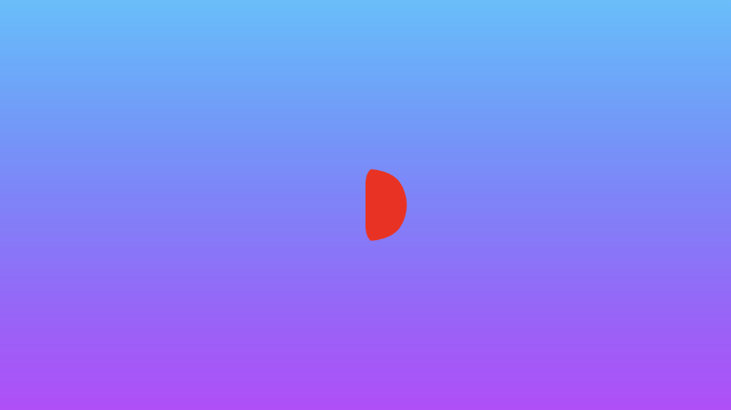
Subtraction: subtract d1 from d2.
vec3 drawScene(vec2 uv) {
  vec3 col = getBackgroundColor(uv);
  float d1 = sdCircle(uv, 0.1, vec2(0., 0.));
  float d2 = sdSquare(uv, 0.1, vec2(0.1, 0));

  float res; // result
  res = max(-d1, d2); // subtraction - subtract d1 from d2

  res = step(0., res); // Same as res > 0. ? 1. : 0.;

  col = mix(vec3(1,0,0), col, res);
  return col;
}
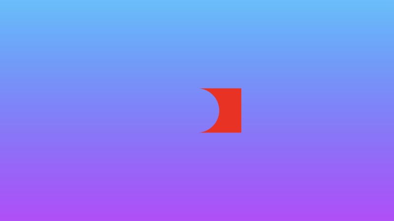
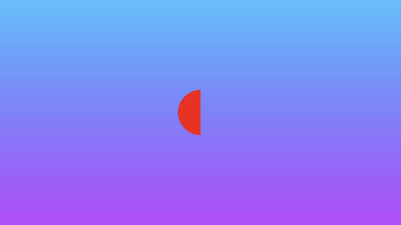
Subtraction: subtract d2 from d1.
vec3 drawScene(vec2 uv) {
  vec3 col = getBackgroundColor(uv);
  float d1 = sdCircle(uv, 0.1, vec2(0., 0.));
  float d2 = sdSquare(uv, 0.1, vec2(0.1, 0));

  float res; // result
  res = max(d1, -d2); // subtraction - subtract d2 from d1

  res = step(0., res); // Same as res > 0. ? 1. : 0.;

  col = mix(vec3(1,0,0), col, res);
  return col;
}
XOR: an exclusive "OR" operation will take the parts of the two shapes that do not intersect with each other.
vec3 drawScene(vec2 uv) {
  vec3 col = getBackgroundColor(uv);
  float d1 = sdCircle(uv, 0.1, vec2(0., 0.));
  float d2 = sdSquare(uv, 0.1, vec2(0.1, 0));

  float res; // result
  res = max(min(d1, d2), -max(d1, d2)); // xor

  res = step(0., res); // Same as res > 0. ? 1. : 0.;

  col = mix(vec3(1,0,0), col, res);
  return col;
}
We can also create "smooth" 2D SDF operations that smoothly blend the edges around where the shapes meet. You'll find these operations to be more applicable when I discuss 3D shapes, but they work in 2D too!
Add the following functions to the top of your code:
// smooth min
float smin(float a, float b, float k) {
  float h = clamp(0.5+0.5*(b-a)/k, 0.0, 1.0);
  return mix(b, a, h) - k*h*(1.0-h);
}

// smooth max
float smax(float a, float b, float k) {
  return -smin(-a, -b, k);
}
Smooth union: combine two shapes together, but smoothly blend the edges where they meet.
vec3 drawScene(vec2 uv) {
  vec3 col = getBackgroundColor(uv);
  float d1 = sdCircle(uv, 0.1, vec2(0., 0.));
  float d2 = sdSquare(uv, 0.1, vec2(0.1, 0));

  float res; // result
  res = smin(d1, d2, 0.05); // smooth union

  res = step(0., res); // Same as res > 0. ? 1. : 0.;

  col = mix(vec3(1,0,0), col, res);
  return col;
}
Smooth intersection: take only the two parts where the two shapes intersect, but smoothly blend the edges where they meet.
vec3 drawScene(vec2 uv) {
  vec3 col = getBackgroundColor(uv);
  float d1 = sdCircle(uv, 0.1, vec2(0., 0.));
  float d2 = sdSquare(uv, 0.1, vec2(0.1, 0));

  float res; // result
  res = smax(d1, d2, 0.05); // smooth intersection

  res = step(0., res); // Same as res > 0. ? 1. : 0.;

  col = mix(vec3(1,0,0), col, res);
  return col;
}
You can find the finished code below. Uncomment out the lines for any of the combination 2D SDF operations you want to see.
// smooth min
float smin(float a, float b, float k) {
  float h = clamp(0.5+0.5*(b-a)/k, 0.0, 1.0);
  return mix(b, a, h) - k*h*(1.0-h);
}

// smooth max
float smax(float a, float b, float k) {
  return -smin(-a, -b, k);
}

vec3 getBackgroundColor(vec2 uv) {
  uv = uv * 0.5 + 0.5; // remap uv from <-0.5,0.5> to <0.25,0.75>
  vec3 gradientStartColor = vec3(1., 0., 1.);
  vec3 gradientEndColor = vec3(0., 1., 1.);
  return mix(gradientStartColor, gradientEndColor, uv.y); // gradient goes from bottom to top
}

float sdCircle(vec2 uv, float r, vec2 offset) {
  float x = uv.x - offset.x;
  float y = uv.y - offset.y;

  return length(vec2(x, y)) - r;
}

float sdSquare(vec2 uv, float size, vec2 offset) {
  float x = uv.x - offset.x;
  float y = uv.y - offset.y;

  return max(abs(x), abs(y)) - size;
}

vec3 drawScene(vec2 uv) {
  vec3 col = getBackgroundColor(uv);
  float d1 = sdCircle(uv, 0.1, vec2(0., 0.));
  float d2 = sdSquare(uv, 0.1, vec2(0.1, 0));

  float res; // result
  res = d1;
  //res = d2;
  //res = min(d1, d2); // union
  //res = max(d1, d2); // intersection
  //res = max(-d1, d2); // subtraction - subtract d1 from d2
  //res = max(d1, -d2); // subtraction - subtract d2 from d1
  //res = max(min(d1, d2), -max(d1, d2)); // xor
  //res = smin(d1, d2, 0.05); // smooth union
  //res = smax(d1, d2, 0.05); // smooth intersection

  res = step(0., res); // Same as res > 0. ? 1. : 0.;

  col = mix(vec3(1,0,0), col, res);
  return col;
}

void mainImage( out vec4 fragColor, in vec2 fragCoord )
{
  vec2 uv = fragCoord/iResolution.xy; // <0, 1>
  uv -= 0.5; // <-0.5,0.5>
  uv.x *= iResolution.x/iResolution.y; // fix aspect ratio

  vec3 col = drawScene(uv);

  fragColor = vec4(col,1.0); // Output to screen
}
Positional 2D SDF Operations
Inigo Quilez's 3D SDFs page describes a set of positional 3D SDF operations, but we can use these operations in 2D as well. I discuss 3D SDF operations later in Part 14. In this tutorial, I'll go over positional 2D SDF operations that can help save us time and increase performance when drawing 2D shapes.
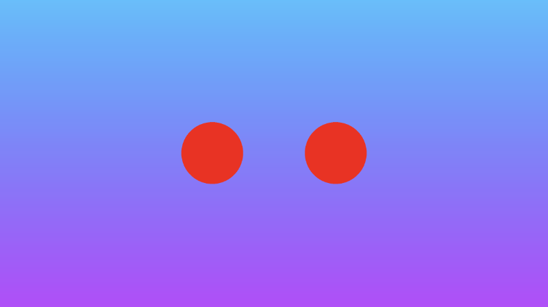
If you're drawing a symmetrical scene, then it may be useful to use the opSymX operation. This operation will create a duplicate 2D shape along the x-axis using the SDF you provide. If we draw a circle at an offset of vec2(0.2, 0), then an equivalent circle will be drawn at vec2(-0.2, 0).
float opSymX(vec2 p, float r)
{
  p.x = abs(p.x);
  return sdCircle(p, r, vec2(0.2, 0));
}

vec3 drawScene(vec2 uv) {
  vec3 col = getBackgroundColor(uv);

  float res; // result
  res = opSymX(uv, 0.1);

  res = step(0., res);
  col = mix(vec3(1,0,0), col, res);
  return col;
}
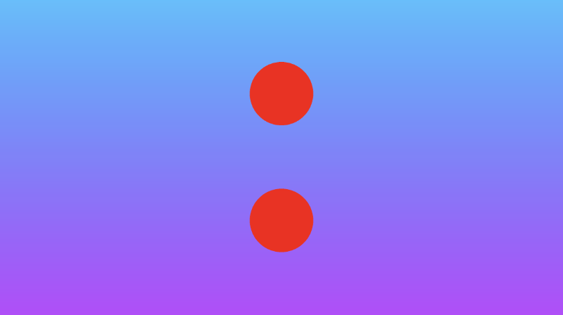
We can also perform a similar operation along the y-axis. Using the opSymY operation, if we draw a circle at an offset of vec2(0, 0.2), then an equivalent circle will be drawn at vec2(0, -0.2).
float opSymY(vec2 p, float r)
{
  p.y = abs(p.y);
  return sdCircle(p, r, vec2(0, 0.2));
}

vec3 drawScene(vec2 uv) {
  vec3 col = getBackgroundColor(uv);

  float res; // result
  res = opSymY(uv, 0.1);

  res = step(0., res);
  col = mix(vec3(1,0,0), col, res);
  return col;
}
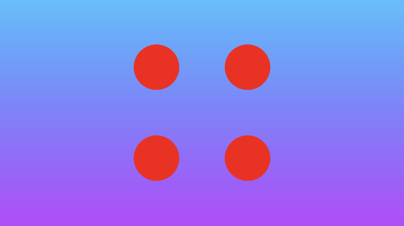
If you want to draw circles along two axes instead of just one, then you can use the opSymXY operation. This will create a duplicate along both the x-axis and y-axis, resulting in four circles. If we draw a circle with an offset of vec2(0.2, 0), then a circle will be drawn at vec2(0.2, 0.2), vec2(0.2, -0.2), vec2(-0.2, -0.2), and vec2(-0.2, 0.2).
float opSymXY(vec2 p, float r)
{
  p = abs(p);
  return sdCircle(p, r, vec2(0.2));
}

vec3 drawScene(vec2 uv) {
  vec3 col = getBackgroundColor(uv);

  float res; // result
  res = opSymXY(uv, 0.1);

  res = step(0., res);
  col = mix(vec3(1,0,0), col, res);
  return col;
}
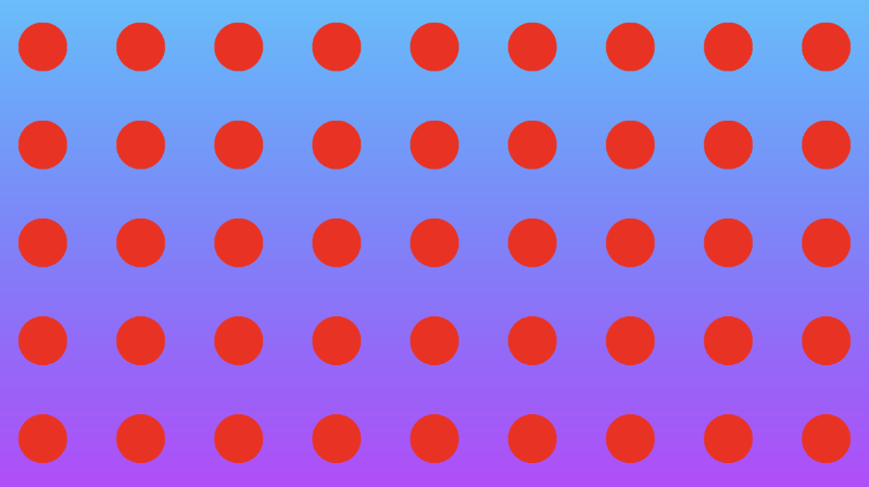
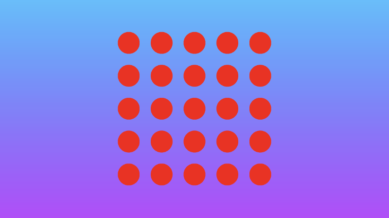
Sometimes, you may want to create an infinite number of 2D objects across one or more axes. You can use the opRep operation to repeat circles along the axes of your choice. The parameter, c, is a vector used to control the spacing between the 2D objects along each axis.
float opRep(vec2 p, float r, vec2 c)
{
  vec2 q = mod(p+0.5*c,c)-0.5*c;
  return sdCircle(q, r, vec2(0));
}

vec3 drawScene(vec2 uv) {
  vec3 col = getBackgroundColor(uv);

  float res; // result
  res = opRep(uv, 0.05, vec2(0.2, 0.2));

  res = step(0., res);
  col = mix(vec3(1,0,0), col, res);
  return col;
}
If you want to repeat the 2D objects only a certain number of times instead of an infinite amount, you can use the opRepLim operation. The parameter, c, is now a float value and still controls the spacing between each repeated 2D object. The parameter, l, is a vector that lets you control how many times the shape should be repeated along a given axis. For example, a value of vec2(2, 2) would draw an extra circle along the positive and negative x-axis and y-axis.
float opRepLim(vec2 p, float r, float c, vec2 l)
{
  vec2 q = p-c*clamp(round(p/c),-l,l);
  return sdCircle(q, r, vec2(0));
}

vec3 drawScene(vec2 uv) {
  vec3 col = getBackgroundColor(uv);

  float res; // result
  res = opRepLim(uv, 0.05, 0.15, vec2(2, 2));

  res = step(0., res);
  col = mix(vec3(1,0,0), col, res);
  return col;
}
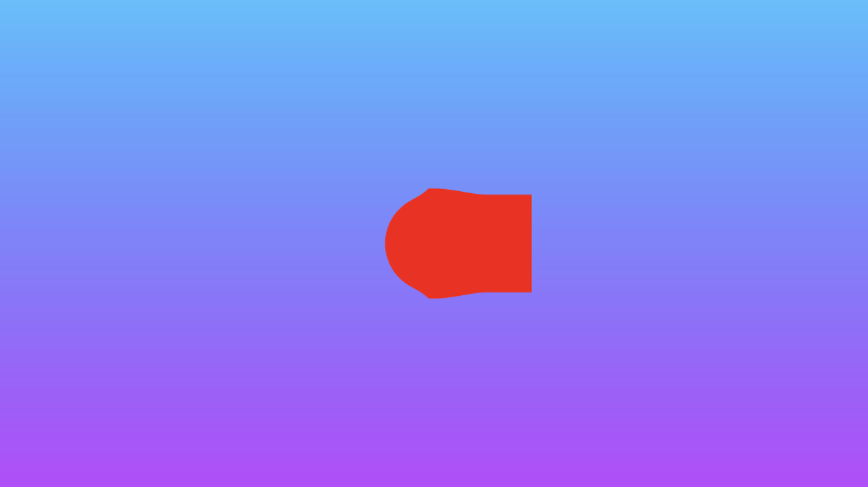
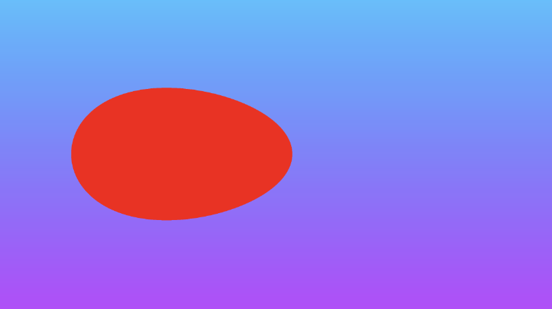
You can also perform deformations or distortions to an SDF by manipulating the value of p, the uv coordinate, and adding it to the value returned from an SDF. Inside the opDisplace operation, you can create any type of mathematical operation you want to displace the value of p and then add that result to the original value you get back from an SDF.
float opDisplace(vec2 p, float r)
{
  float d1 = sdCircle(p, r, vec2(0));
  float s = 0.5; // scaling factor

  float d2 = sin(s * p.x * 1.8); // Some arbitrary values I played around with

  return d1 + d2;
}

vec3 drawScene(vec2 uv) {
  vec3 col = getBackgroundColor(uv);

  float res; // result
  res = opDisplace(uv, 0.1); // Kinda looks like an egg

  res = step(0., res);
  col = mix(vec3(1,0,0), col, res);
  return col;
}
You can find the finished code below. Uncomment out the lines for any of the positional 2D SDF operations you want to see.
vec3 getBackgroundColor(vec2 uv) {
  uv = uv * 0.5 + 0.5; // remap uv from <-0.5,0.5> to <0.25,0.75>
  vec3 gradientStartColor = vec3(1., 0., 1.);
  vec3 gradientEndColor = vec3(0., 1., 1.);
  return mix(gradientStartColor, gradientEndColor, uv.y); // gradient goes from bottom to top
}

float sdCircle(vec2 uv, float r, vec2 offset) {
  float x = uv.x - offset.x;
  float y = uv.y - offset.y;

  return length(vec2(x, y)) - r;
}

float opSymX(vec2 p, float r)
{
  p.x = abs(p.x);
  return sdCircle(p, r, vec2(0.2, 0));
}

float opSymY(vec2 p, float r)
{
  p.y = abs(p.y);
  return sdCircle(p, r, vec2(0, 0.2));
}

float opSymXY(vec2 p, float r)
{
  p = abs(p);
  return sdCircle(p, r, vec2(0.2));
}

float opRep(vec2 p, float r, vec2 c)
{
  vec2 q = mod(p+0.5*c,c)-0.5*c;
  return sdCircle(q, r, vec2(0));
}

float opRepLim(vec2 p, float r, float c, vec2 l)
{
  vec2 q = p-c*clamp(round(p/c),-l,l);
  return sdCircle(q, r, vec2(0));
}

float opDisplace(vec2 p, float r)
{
  float d1 = sdCircle(p, r, vec2(0));
  float s = 0.5; // scaling factor

  float d2 = sin(s * p.x * 1.8); // Some arbitrary values I played around with

  return d1 + d2;
}

vec3 drawScene(vec2 uv) {
  vec3 col = getBackgroundColor(uv);

  float res; // result
  res = opSymX(uv, 0.1);
  //res = opSymY(uv, 0.1);
  //res = opSymXY(uv, 0.1);
  //res = opRep(uv, 0.05, vec2(0.2, 0.2));
  //res = opRepLim(uv, 0.05, 0.15, vec2(2, 2));
  //res = opDisplace(uv, 0.1);

  res = step(0., res);
  col = mix(vec3(1,0,0), col, res);
  return col;
}

void mainImage( out vec4 fragColor, in vec2 fragCoord )
{
  vec2 uv = fragCoord/iResolution.xy; // <0, 1>
  uv -= 0.5; // <-0.5,0.5>
  uv.x *= iResolution.x/iResolution.y; // fix aspect ratio

  vec3 col = drawScene(uv);

  fragColor = vec4(col,1.0); // Output to screen
}
Anti-aliasing
If you want to add any anti-aliasing, then you can use the smoothstep function to smooth out the edges of your shapes. The smoothstep(edge0, edge1, x) function accepts three parameters and performs a Hermite interpolation between zero and one when edge0 < x < edge1 .
edge0: Specifies the value of the lower edge of the Hermite function.

edge1: Specifies the value of the upper edge of the Hermite function.

x: Specifies the source value for interpolation.

t = clamp((x - edge0) / (edge1 - edge0), 0.0, 1.0);
return t * t * (3.0 - 2.0 * t);
If you're still confused, this page from The Book of Shaders may help you visualize the smoothstep function. Essentially, it behaves like the step function with a few extra steps (no pun intended) 😂.
Let's replace the step function with the smoothstep function to see how the result between a union of a circle and square behaves.
vec3 getBackgroundColor(vec2 uv) {
  uv = uv * 0.5 + 0.5; // remap uv from <-0.5,0.5> to <0.25,0.75>
  vec3 gradientStartColor = vec3(1., 0., 1.);
  vec3 gradientEndColor = vec3(0., 1., 1.);
  return mix(gradientStartColor, gradientEndColor, uv.y); // gradient goes from bottom to top
}

float sdCircle(vec2 uv, float r, vec2 offset) {
  float x = uv.x - offset.x;
  float y = uv.y - offset.y;

  return length(vec2(x, y)) - r;
}

float sdSquare(vec2 uv, float size, vec2 offset) {
  float x = uv.x - offset.x;
  float y = uv.y - offset.y;

  return max(abs(x), abs(y)) - size;
}

vec3 drawScene(vec2 uv) {
  vec3 col = getBackgroundColor(uv);
  float d1 = sdCircle(uv, 0.1, vec2(0., 0.));
  float d2 = sdSquare(uv, 0.1, vec2(0.1, 0));

  float res; // result
  res = min(d1, d2); // union

  res = smoothstep(0., 0.02, res); // antialias entire result

  col = mix(vec3(1,0,0), col, res);
  return col;
}

void mainImage( out vec4 fragColor, in vec2 fragCoord )
{
  vec2 uv = fragCoord/iResolution.xy; // <0, 1>
  uv -= 0.5; // <-0.5,0.5>
  uv.x *= iResolution.x/iResolution.y; // fix aspect ratio

  vec3 col = drawScene(uv);

  fragColor = vec4(col,1.0); // Output to screen
}
We end up with a shape that is slightly blurred around the edges.

The smoothstep function helps us create smooth transitions between colors, useful for implementing anti-aliasing. You may also see people use smoothstep to create emissive objects or neon glow effects. It is used very often in shaders.
Drawing a Heart ❤️
In this section, I'll teach you how to draw a heart using Shadertoy. Keep in mind that there are multiple styles of hearts. I'll show you how to create just one particular style of heart using an equation from Wolfram MathWorld.
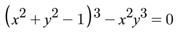
If we want to apply an offset to this heart curve, then we need to subtract it from the x-component and y-component before applying any sort of operation (such as exponentiation) on them.
s = x - offsetX
t = y - offsetY

(s^2 + t^2 - 1)^3 - s^2 * t^3 = 0

x = x-coordinate on graph
y = y-coordinate on graph
You can play around with offsets on a heart curve using the graph I created on Desmos.
Now, how do we create an SDF for a heart in Shadertoy? We simply set the left-hand side (LHS) of the equation equal to the distance, d. Then, it's the same process as we learned in Part 4.
float sdHeart(vec2 uv, float size, vec2 offset) {
  float x = uv.x - offset.x;
  float y = uv.y - offset.y;
  float xx = x * x;
  float yy = y * y;
  float yyy = yy * y;
  float group = xx + yy - size;
  float d = group * group * group - xx * yyy;

  return d;
}

vec3 drawScene(vec2 uv) {
  vec3 col = vec3(1);
  float heart = sdHeart(uv, 0.04, vec2(0));

  col = mix(vec3(1, 0, 0), col, step(0., heart));

  return col;
}

void mainImage( out vec4 fragColor, in vec2 fragCoord )
{
  vec2 uv = fragCoord/iResolution.xy; // <0, 1>
  uv -= 0.5; // <-0.5,0.5>
  uv.x *= iResolution.x/iResolution.y; // fix aspect ratio

  vec3 col = drawScene(uv);

  // Output to screen
  fragColor = vec4(col,1.0);
}

Understanding the pow Function
You may be wondering why I created the sdHeart function in such a weird manner. Why not use the pow function that is available to us? The pow(x,y) function takes in a value, x, and raises it to the power of y.
If you tried using the pow function, you'll see right away how odd the heart behaves.
float sdHeart(vec2 uv, float size, vec2 offset) {
  float x = uv.x - offset.x;
  float y = uv.y - offset.y;
  float group = pow(x,2.) + pow(y,2.) - size;
  float d = pow(group,3.) - pow(x,2.) * pow(y,3.);

  return d;
}
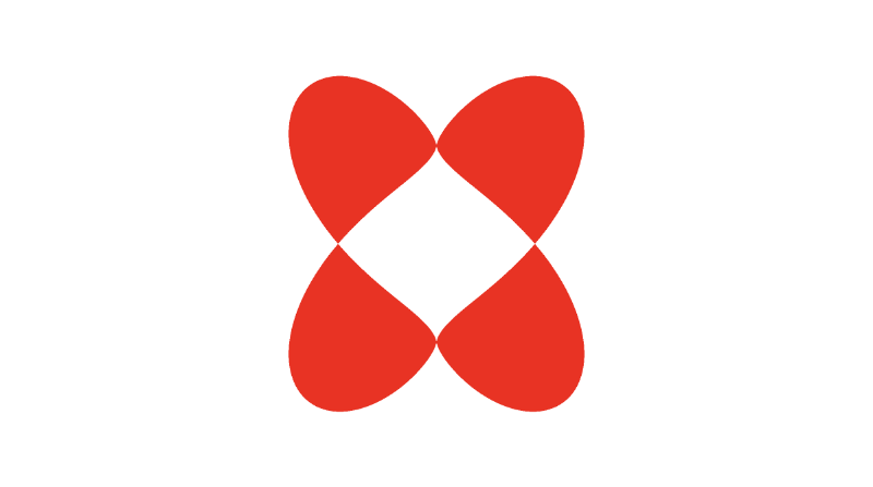
Well, that doesn't look right 🤔. If you sent that to someone on Valentine's Day, they might think it's an inkblot test.
So why does the pow(x,y) function behave so strangely? If you look closer at the documentation for this function, then you'll see that this function returns undefined if x is less than zero or if both x equals zero and y is less than or equal to zero.
Keep in mind that the implementation of the pow function varies by compiler and hardware, so you may not encounter this issue when developing shaders for other platforms outside Shadertoy, or you may experience different issues.
Because our coordinate system is set up to have negative values for x and y, we sometimes get undefined as a result of the pow function. In Shadertoy, the compiler will use undefined in mathematical operations which will then lead to confusing results.
We can experiment with how undefined behaves with different arithmetic operations by debugging the canvas using color. Let's try adding a number to undefined:
void mainImage( out vec4 fragColor, in vec2 fragCoord )
{
  vec2 uv = fragCoord/iResolution.xy; // <0, 1>
  uv -= 0.5; // <-0.5,0.5>

  vec3 col = vec3(pow(-0.5, 1.));
  col += 0.5;

  fragColor = vec4(col,1.0);
  // Screen is gray which means undefined is treated as zero
}
Let's try subtracting a number from undefined:
void mainImage( out vec4 fragColor, in vec2 fragCoord )
{
  vec2 uv = fragCoord/iResolution.xy; // <0, 1>
  uv -= 0.5; // <-0.5,0.5>

  vec3 col = vec3(pow(-0.5, 1.));
  col -= -0.5;

  fragColor = vec4(col,1.0);
  // Screen is gray which means undefined is treated as zero
}
Let's try multiplying a number by undefined:
void mainImage( out vec4 fragColor, in vec2 fragCoord )
{
  vec2 uv = fragCoord/iResolution.xy; // <0, 1>
  uv -= 0.5; // <-0.5,0.5>

  vec3 col = vec3(pow(-0.5, 1.));
  col *= 1.;

  fragColor = vec4(col,1.0);
  // Screen is black which means undefined is treated as zero
}
Let's try dividing undefined by a number:
void mainImage( out vec4 fragColor, in vec2 fragCoord )
{
  vec2 uv = fragCoord/iResolution.xy; // <0, 1>
  uv -= 0.5; // <-0.5,0.5>

  vec3 col = vec3(pow(-0.5, 1.));
  col /= 1.;

  fragColor = vec4(col,1.0);
  // Screen is black which means undefined is treated as zero
}
From the observations we've gathered, we can conclude that undefined is treated as a value of zero when used in arithmetic operations. However, this could still vary by compiler and graphics hardware. Therefore, you need to be careful how you use the pow function in your shader code.
If you want to square a value, a common trick is to use the dot function to compute the dot product between a vector and itself. This lets us rewrite the sdHeart function to be a bit cleaner:
float sdHeart(vec2 uv, float size, vec2 offset) {
  float x = uv.x - offset.x;
  float y = uv.y - offset.y;
  float group = dot(x,x) + dot(y,y) - size;
  float d = group * dot(group, group) - dot(x,x) * dot(y,y) * y;

  return d;
}
Calling dot(x,x) is the same as squaring the value of x, but you don't have to deal with the hassles of the pow function.
Using the sdStar5 SDF
Inigo Quilez has created many 2D SDFs and 3D SDFs that developers across Shadertoy utilize. In this section, I'll discuss how we can use his 2D SDF list together with techniques we learned in Part 4 of my Shadertoy series to draw 2D shapes.
When creating shapes using SDFs, they are commonly referred to as "primitives" because they form the building blocks for creating more abstract shapes. For 2D, it's pretty simple to draw shapes on the canvas, but it'll become more complex when we discuss 3D shapes.
Let's practice with a star SDF because drawing stars is always fun. Navigate to Inigo Quilez's website and scroll down to the SDF called "Star 5 - exact". It should have the following definition:
float sdStar5(in vec2 p, in float r, in float rf)
{
  const vec2 k1 = vec2(0.809016994375, -0.587785252292);
  const vec2 k2 = vec2(-k1.x,k1.y);
  p.x = abs(p.x);
  p -= 2.0*max(dot(k1,p),0.0)*k1;
  p -= 2.0*max(dot(k2,p),0.0)*k2;
  p.x = abs(p.x);
  p.y -= r;
  vec2 ba = rf*vec2(-k1.y,k1.x) - vec2(0,1);
  float h = clamp( dot(p,ba)/dot(ba,ba), 0.0, r );
  return length(p-ba*h) * sign(p.y*ba.x-p.x*ba.y);
}
Don't worry about the in qualifiers in the function. You can remove them if you want, since in is the default qualifier if none is specified.
Let's create a new Shadertoy shader with the following code:
float sdStar5(in vec2 p, in float r, in float rf)
{
const vec2 k1 = vec2(0.809016994375, -0.587785252292);
const vec2 k2 = vec2(-k1.x,k1.y);
p.x = abs(p.x);
p -= 2.0*max(dot(k1,p),0.0)*k1;
p -= 2.0*max(dot(k2,p),0.0)*k2;
p.x = abs(p.x);
p.y -= r;
vec2 ba = rf*vec2(-k1.y,k1.x) - vec2(0,1);
float h = clamp( dot(p,ba)/dot(ba,ba), 0.0, r );
return length(p-ba*h) * sign(p.y*ba.x-p.x*ba.y);
}
vec3 drawScene(vec2 uv) {
vec3 col = vec3(0);
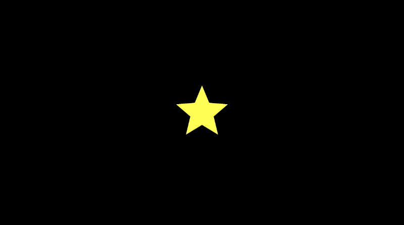
float star = sdStar5(uv, 0.12, 0.45);
col = mix(vec3(1, 1, 0), col, step(0., star));
return col;
}
void mainImage( out vec4 fragColor, in vec2 fragCoord )
{
vec2 uv = fragCoord/iResolution.xy; // <0, 1>
uv -= 0.5; // <-0.5,0.5>
uv.x *= iResolution.x/iResolution.y; // fix aspect ratio
vec3 col = drawScene(uv);
// Output to screen
fragColor = vec4(col,1.0);
}
When we run this code, you should be able to see a bright yellow star! ⭐
One thing is missing though. We need to add an offset at the beginning of the sdStar5 function by shifting the UV coordinates a bit. We can add a new parameter called offset, and we can subtract this offset from the vector, p, which represents the UV coordinates we passed into this function.
Our finished code should like this this:
float sdStar5(in vec2 p, in float r, in float rf, vec2 offset)
{
  p -= offset; // This will subtract offset.x from p.x and subtract offset.y from p.y
  const vec2 k1 = vec2(0.809016994375, -0.587785252292);
  const vec2 k2 = vec2(-k1.x,k1.y);
  p.x = abs(p.x);
  p -= 2.0*max(dot(k1,p),0.0)*k1;
  p -= 2.0*max(dot(k2,p),0.0)*k2;
  p.x = abs(p.x);
  p.y -= r;
  vec2 ba = rf*vec2(-k1.y,k1.x) - vec2(0,1);
  float h = clamp( dot(p,ba)/dot(ba,ba), 0.0, r );
  return length(p-ba*h) * sign(p.y*ba.x-p.x*ba.y);
}

vec3 drawScene(vec2 uv) {
  vec3 col = vec3(0);
  float star = sdStar5(uv, 0.12, 0.45, vec2(0.2, 0)); // Add an offset to shift the star's position

  col = mix(vec3(1, 1, 0), col, step(0., star));

  return col;
}

void mainImage( out vec4 fragColor, in vec2 fragCoord )
{
  vec2 uv = fragCoord/iResolution.xy; // <0, 1>
  uv -= 0.5; // <-0.5,0.5>
  uv.x *= iResolution.x/iResolution.y; // fix aspect ratio

  vec3 col = drawScene(uv);

  // Output to screen
  fragColor = vec4(col,1.0);
}
Using the sdBox SDF
It's quite common to draw boxes/rectangles, so we'll select the SDF titled "Box - exact." It has the following definition:
float sdBox( in vec2 p, in vec2 b )
{
  vec2 d = abs(p)-b;
  return length(max(d,0.0)) + min(max(d.x,d.y),0.0);
}
We'll add an offset parameter to the function declaration.
float sdBox( in vec2 p, in vec2 b, vec2 offset )
{
  p -= offset;
  vec2 d = abs(p)-b;
  return length(max(d,0.0)) + min(max(d.x,d.y),0.0);
}
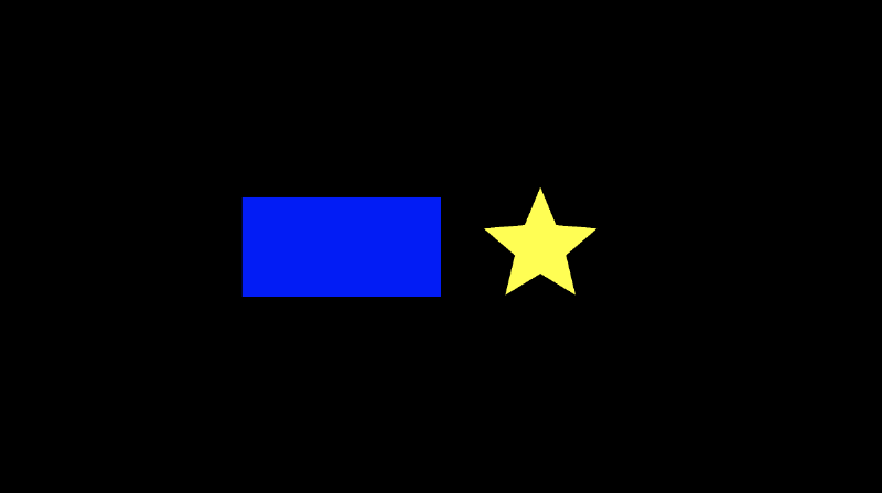
Now, we should be able to render both the box and star without any issues:
float sdBox( in vec2 p, in vec2 b, vec2 offset )
{
  p -= offset;
  vec2 d = abs(p)-b;
  return length(max(d,0.0)) + min(max(d.x,d.y),0.0);
}

float sdStar5(in vec2 p, in float r, in float rf, vec2 offset)
{
  p -= offset; // This will subtract offset.x from p.x and subtract offset.y from p.y
  const vec2 k1 = vec2(0.809016994375, -0.587785252292);
  const vec2 k2 = vec2(-k1.x,k1.y);
  p.x = abs(p.x);
  p -= 2.0*max(dot(k1,p),0.0)*k1;
  p -= 2.0*max(dot(k2,p),0.0)*k2;
  p.x = abs(p.x);
  p.y -= r;
  vec2 ba = rf*vec2(-k1.y,k1.x) - vec2(0,1);
  float h = clamp( dot(p,ba)/dot(ba,ba), 0.0, r );
  return length(p-ba*h) * sign(p.y*ba.x-p.x*ba.y);
}

vec3 drawScene(vec2 uv) {
  vec3 col = vec3(0);
  float box = sdBox(uv, vec2(0.2, 0.1), vec2(-0.2, 0));
  float star = sdStar5(uv, 0.12, 0.45, vec2(0.2, 0));

  col = mix(vec3(1, 1, 0), col, step(0., star));
  col = mix(vec3(0, 0, 1), col, step(0., box));

  return col;
}

void mainImage( out vec4 fragColor, in vec2 fragCoord )
{
  vec2 uv = fragCoord/iResolution.xy; // <0, 1>
  uv -= 0.5; // <-0.5,0.5>
  uv.x *= iResolution.x/iResolution.y; // fix aspect ratio

  vec3 col = drawScene(uv);

  // Output to screen
  fragColor = vec4(col,1.0);
}
With only a few small tweaks, we can pick many 2D SDFs from Inigo Quilez's website and draw them to the canvas with an offset.
Note, however, that some of the SDFs require functions defined on his 3D SDF page:
float dot2( in vec2 v ) { return dot(v,v); }
float dot2( in vec3 v ) { return dot(v,v); }
float ndot( in vec2 a, in vec2 b ) { return a.x*b.x - a.y*b.y; }
Using the sdSegment SDF
Some of the 2D SDFs on Inigo Quilez's website are for segments or curves, so we may need to alter our approach slightly. Let's look at the SDF titled "Segment - exact". It has the following definition:
float sdSegment( in vec2 p, in vec2 a, in vec2 b )
{
  vec2 pa = p-a, ba = b-a;
  float h = clamp( dot(pa,ba)/dot(ba,ba), 0.0, 1.0 );
  return length( pa - ba*h );
}
Let's try using this SDF and see what happens.
float sdSegment( in vec2 p, in vec2 a, in vec2 b )
{
  vec2 pa = p-a, ba = b-a;
  float h = clamp( dot(pa,ba)/dot(ba,ba), 0.0, 1.0 );
  return length( pa - ba*h );
}

vec3 drawScene(vec2 uv) {
  vec3 col = vec3(0);
  float segment = sdSegment(uv, vec2(0, 0), vec2(0, .2));

  col = mix(vec3(1, 1, 1), col, step(0., segment));

  return col;
}

void mainImage( out vec4 fragColor, in vec2 fragCoord )
{
  vec2 uv = fragCoord/iResolution.xy; // <0, 1>
  uv -= 0.5; // <-0.5,0.5>
  uv.x *= iResolution.x/iResolution.y; // fix aspect ratio

  vec3 col = drawScene(uv);

  // Output to screen
  fragColor = vec4(col,1.0);
}
When we run this code, we'll see a completely black canvas. Some SDFs require us to look at the code a bit more closely. Currently, the segment is too thin to see in our canvas. To give the segment some thickness, we can subtract a value from the returned distance.
float sdSegment( in vec2 p, in vec2 a, in vec2 b )
{
  vec2 pa = p-a, ba = b-a;
  float h = clamp( dot(pa,ba)/dot(ba,ba), 0.0, 1.0 );
  return length( pa - ba*h );
}

vec3 drawScene(vec2 uv) {
  vec3 col = vec3(0);
  float segment = sdSegment(uv, vec2(0, 0), vec2(0, 0.2));

  col = mix(vec3(1, 1, 1), col, step(0., segment - 0.02)); // Subtract 0.02 from the returned "signed distance" value of the segment

  return col;
}

void mainImage( out vec4 fragColor, in vec2 fragCoord )
{
  vec2 uv = fragCoord/iResolution.xy; // <0, 1>
  uv -= 0.5; // <-0.5,0.5>
  uv.x *= iResolution.x/iResolution.y; // fix aspect ratio

  vec3 col = drawScene(uv);

  // Output to screen
  fragColor = vec4(col,1.0);
}
Now, we can see our segment appear! It starts at the coordinate, (0, 0), and ends at (0, 0.2). Play around with the input vectors, a and b, inside the call to the sdSegment function to move the segment around and stretch it different ways. You can replace 0.02 with another number if you want to make the segment thinner or wider.

You can also use the smoothstep function to make the segment look blurry around the edges.
float sdSegment( in vec2 p, in vec2 a, in vec2 b )
{
  vec2 pa = p-a, ba = b-a;
  float h = clamp( dot(pa,ba)/dot(ba,ba), 0.0, 1.0 );
  return length( pa - ba*h );
}

vec3 drawScene(vec2 uv) {
  vec3 col = vec3(0);
  float segment = sdSegment(uv, vec2(0, 0), vec2(0, .2));

  col = mix(vec3(1, 1, 1), col, smoothstep(0., 0.02, segment));

  return col;
}

void mainImage( out vec4 fragColor, in vec2 fragCoord )
{
  vec2 uv = fragCoord/iResolution.xy; // <0, 1>
  uv -= 0.5; // <-0.5,0.5>
  uv.x *= iResolution.x/iResolution.y; // fix aspect ratio

  vec3 col = drawScene(uv);

  // Output to screen
  fragColor = vec4(col,1.0);
}
The segment now looks like it's glowing!

Using the sdBezier SDF
Inigo Quilez's website also has an SDF for Bézier curves. More specifically, he has an SDF for a Quadratic Bézier curve. Look for the SDF titled "Quadratic Bezier - exact". It has the following definition:
float sdBezier( in vec2 pos, in vec2 A, in vec2 B, in vec2 C )
{
    vec2 a = B - A;
    vec2 b = A - 2.0*B + C;
    vec2 c = a * 2.0;
    vec2 d = A - pos;
    float kk = 1.0/dot(b,b);
    float kx = kk * dot(a,b);
    float ky = kk * (2.0*dot(a,a)+dot(d,b)) / 3.0;
    float kz = kk * dot(d,a);
    float res = 0.0;
    float p = ky - kx*kx;
    float p3 = p*p*p;
    float q = kx*(2.0*kx*kx-3.0*ky) + kz;
    float h = q*q + 4.0*p3;
    if( h >= 0.0)
    {
        h = sqrt(h);
        vec2 x = (vec2(h,-h)-q)/2.0;
        vec2 uv = sign(x)*pow(abs(x), vec2(1.0/3.0));
        float t = clamp( uv.x+uv.y-kx, 0.0, 1.0 );
        res = dot2(d + (c + b*t)*t);
    }
    else
    {
        float z = sqrt(-p);
        float v = acos( q/(p*z*2.0) ) / 3.0;
        float m = cos(v);
        float n = sin(v)*1.732050808;
        vec3  t = clamp(vec3(m+m,-n-m,n-m)*z-kx,0.0,1.0);
        res = min( dot2(d+(c+b*t.x)*t.x),
                   dot2(d+(c+b*t.y)*t.y) );
        // the third root cannot be the closest
        // res = min(res,dot2(d+(c+b*t.z)*t.z));
    }
    return sqrt( res );
}
That's quite a large function! Notice that this function uses a utility function, dot2. This is defined on his 3D SDF page.
float dot2( in vec2 v ) { return dot(v,v); }
Quadratic Bézier curves accept three control points. In 2D, each control point will be a vec2 value with an x-component and y-component. You can play around with the control points using a graph I created on Desmos.
Like the sdSegment, we will have to subtract a small value from the returned "signed distance" to see the curve properly. Let's see how to draw a Quadratic Bézier curve using GLSL code:
float dot2( in vec2 v ) { return dot(v,v); }

float sdBezier( in vec2 pos, in vec2 A, in vec2 B, in vec2 C )
{
    vec2 a = B - A;
    vec2 b = A - 2.0*B + C;
    vec2 c = a * 2.0;
    vec2 d = A - pos;
    float kk = 1.0/dot(b,b);
    float kx = kk * dot(a,b);
    float ky = kk * (2.0*dot(a,a)+dot(d,b)) / 3.0;
    float kz = kk * dot(d,a);
    float res = 0.0;
    float p = ky - kx*kx;
    float p3 = p*p*p;
    float q = kx*(2.0*kx*kx-3.0*ky) + kz;
    float h = q*q + 4.0*p3;
    if( h >= 0.0)
    {
        h = sqrt(h);
        vec2 x = (vec2(h,-h)-q)/2.0;
        vec2 uv = sign(x)*pow(abs(x), vec2(1.0/3.0));
        float t = clamp( uv.x+uv.y-kx, 0.0, 1.0 );
        res = dot2(d + (c + b*t)*t);
    }
    else
    {
        float z = sqrt(-p);
        float v = acos( q/(p*z*2.0) ) / 3.0;
        float m = cos(v);
        float n = sin(v)*1.732050808;
        vec3  t = clamp(vec3(m+m,-n-m,n-m)*z-kx,0.0,1.0);
        res = min( dot2(d+(c+b*t.x)*t.x),
                   dot2(d+(c+b*t.y)*t.y) );
        // the third root cannot be the closest
        // res = min(res,dot2(d+(c+b*t.z)*t.z));
    }
    return sqrt( res );
}

vec3 drawScene(vec2 uv) {
    vec3 col = vec3(0);
    vec2 A = vec2(0, 0);
    vec2 B = vec2(0.2, 0);
    vec2 C = vec2(0.2, 0.2);
    float curve = sdBezier(uv, A, B, C);

    col = mix(vec3(1, 1, 1), col, step(0., curve - 0.01));

    return col;
}

void mainImage( out vec4 fragColor, in vec2 fragCoord )
{
    vec2 uv = fragCoord/iResolution.xy; // <0, 1>
    uv -= 0.5; // <-0.5,0.5>
    uv.x *= iResolution.x/iResolution.y; // fix aspect ratio

    vec3 col = drawScene(uv);

    // Output to screen
    fragColor = vec4(col,1.0);
}
When you run the code, you should see the Quadratic Bézier curve appear.
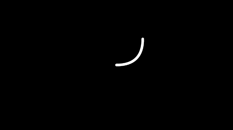
Try playing around with the control points! Remember! You can use my Desmos graph to help!
You can use 2D operations together with Bézier curves to create interesting effects. We can subtract two Bézier curves from a circle to get some kind of tennis ball 🎾. It's up to you to explore what all you can create with the tools presented to you!

Below you can find the finished code used to make the tennis ball:
vec3 getBackgroundColor(vec2 uv) {
  uv = uv * 0.5 + 0.5; // remap uv from <-0.5,0.5> to <0.25,0.75>
  vec3 gradientStartColor = vec3(1., 0., 1.);
  vec3 gradientEndColor = vec3(0., 1., 1.);
  return mix(gradientStartColor, gradientEndColor, uv.y); // gradient goes from bottom to top
}

float sdCircle(vec2 uv, float r, vec2 offset) {
  float x = uv.x - offset.x;
  float y = uv.y - offset.y;

  return length(vec2(x, y)) - r;
}

float dot2( in vec2 v ) { return dot(v,v); }

float sdBezier( in vec2 pos, in vec2 A, in vec2 B, in vec2 C )
{
    vec2 a = B - A;
    vec2 b = A - 2.0*B + C;
    vec2 c = a * 2.0;
    vec2 d = A - pos;
    float kk = 1.0/dot(b,b);
    float kx = kk * dot(a,b);
    float ky = kk * (2.0*dot(a,a)+dot(d,b)) / 3.0;
    float kz = kk * dot(d,a);
    float res = 0.0;
    float p = ky - kx*kx;
    float p3 = p*p*p;
    float q = kx*(2.0*kx*kx-3.0*ky) + kz;
    float h = q*q + 4.0*p3;
    if( h >= 0.0)
    {
        h = sqrt(h);
        vec2 x = (vec2(h,-h)-q)/2.0;
        vec2 uv = sign(x)*pow(abs(x), vec2(1.0/3.0));
        float t = clamp( uv.x+uv.y-kx, 0.0, 1.0 );
        res = dot2(d + (c + b*t)*t);
    }
    else
    {
        float z = sqrt(-p);
        float v = acos( q/(p*z*2.0) ) / 3.0;
        float m = cos(v);
        float n = sin(v)*1.732050808;
        vec3  t = clamp(vec3(m+m,-n-m,n-m)*z-kx,0.0,1.0);
        res = min( dot2(d+(c+b*t.x)*t.x),
                   dot2(d+(c+b*t.y)*t.y) );
        // the third root cannot be the closest
        // res = min(res,dot2(d+(c+b*t.z)*t.z));
    }
    return sqrt( res );
}

vec3 drawScene(vec2 uv) {
  vec3 col = getBackgroundColor(uv);
  float d1 = sdCircle(uv, 0.2, vec2(0., 0.));
  vec2 A = vec2(-0.2, 0.2);
  vec2 B = vec2(0, 0);
  vec2 C = vec2(0.2, 0.2);
  float d2 = sdBezier(uv, A, B, C) - 0.03;
  float d3 = sdBezier(uv*vec2(1,-1), A, B, C) - 0.03;

  float res; // result
  res = max(d1, -d2); // subtraction - subtract d2 from d1
  res = max(res, -d3); // subtraction - subtract d3 from the result

  res = smoothstep(0., 0.01, res); // antialias entire result

  col = mix(vec3(.8,.9,.2), col, res);
  return col;
}

void mainImage( out vec4 fragColor, in vec2 fragCoord )
{
  vec2 uv = fragCoord/iResolution.xy; // <0, 1>
  uv -= 0.5; // <-0.5,0.5>
  uv.x *= iResolution.x/iResolution.y; // fix aspect ratio

  vec3 col = drawScene(uv);

  fragColor = vec4(col,1.0); // Output to screen
}
Conclusion
In this tutorial, we learned how to show more love to our shaders by drawing a heart ❤️ and other shapes. We learned how to draw stars, segments, and Quadratic Bézier curves. Of course, my technique for drawing shapes with 2D SDFs is just a personal preference. There are multiple ways we can draw 2D shapes to the canvas. We also learned how to combine primitive shapes together to create more complex shapes. In the next article, we'll begin learning how to draw 3D shapes and scenes using raymarching! 🎉